


12-98 11 21322K
GC150 SERIES DIRECT VENT GAS APPLIANCE
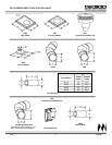
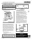
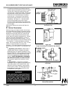
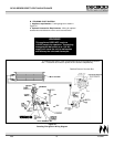
To install the termination cap, slide the cap vent
sections into the vent sections as shown in Figures
10A and 10B. Secure the cap flush to the wall
using the eight 1" fasteners provided. Seal the cap
to the wall with a mastic such as silicone caulking.
Fasten the inner vent with three 1/2" screws to
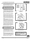
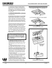
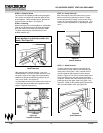
secure the vent. (An optional CS cap shield is
required if the cap is located in an area of easy
accessibility. See Figure 11.) Vent termination
must not be recessed into the wall or siding.
Be sure to follow all termination cap location mini-
mum dimensions that have been discussed on the
previous page.
Skip section B below and continue with Step 4 on
page 13.
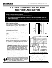
B. Vertical Termination
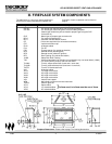
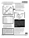
When planning your fireplace location, the vent sys-
tem construction and necessary clearances must be
considered. The following figures are the maximum
distances from the base of the unit, as well as the
minimum air space clearances that must be main-
tained: Maximum straight unsupported rise - 25 feet;
maximum horizontal unsupported run - 3 feet; air
space clearances around vertical venting - 1" on all
sides; air space clearances around horizontal venting
- 3" on top and 1" on sides and bottom; maximum
height - 40' from the base of the unit. Every 1' of hori-
zontal run requires at least 2' of vertical rise.
(Example: a 12' overall installation height may be off-
set as much as 6' horizontally.) The maximum is 20
feet.
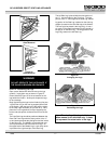
1. Assembling vent sections. Attach either a
15942B (starter elbow) or straight vent section
(depending upon your specific installation) to the
top of the appliance. Secure with the three screws
supplied. Use only vent supplied with this appli-
ance and the appropriate number of direct vent
sections. MAINTAIN MINIMUM CLEARANCES
OR GREATER AROUND THE VENT SYSTEM.
Do not pack air spaces with insulation or other
material.
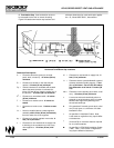
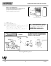
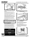
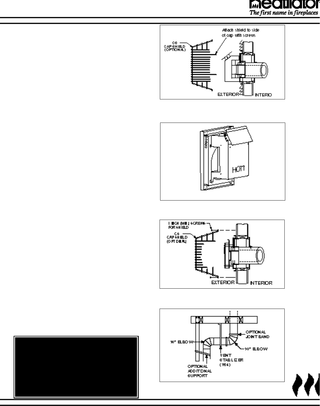
a. Using elbows. To bypass any overhead
obstructions, the vent system may be offset using
a 90° elbow (VK5) or a 45° elbow (EL45). Vent
stabilizers (VS4) have straps for securing these
parts to joists or rafters. Plumbers tape may be
purchased locally and used in conjunction with
vent stabilizers. See Figure12.
Figure 10A
Termination Cap
Figure 10B
Proper Positioning of Termination Cap & Shield
Figure 11
Cap Shield
Figure 12
Elbows with stabilizer
WARNING!
WHEN HORIZONTAL RUNS EXCEEDING 3'
IN LENGTH ARE USED BETWEEN AN OFF-
SET/RETURN, STRUCTURAL SUPPORT
(VS4) MUST BE USED TO REDUCE OFF-
CENTER LOADING AND PREVENT VENT
SECTIONS FROM SEPARATING.