


12-98 13 21322K
GC150 SERIES DIRECT VENT GAS APPLIANCE
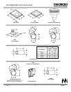
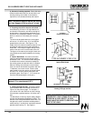
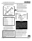
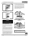
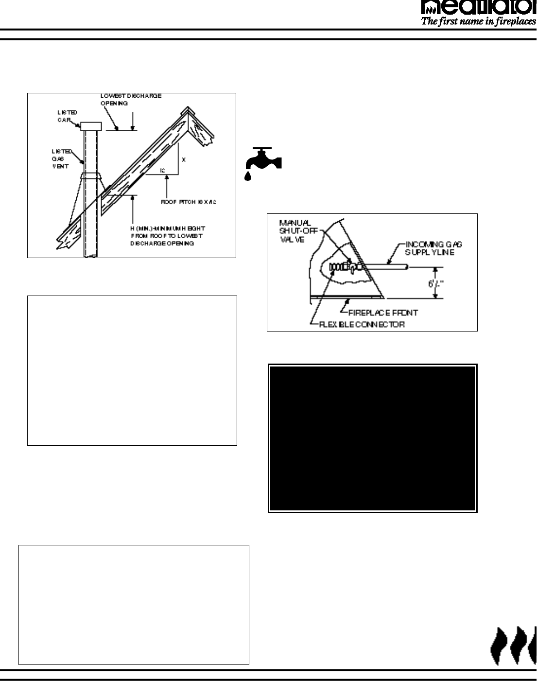
10. Termination cap. Major building codes spec-
ify a minimum venting system height above the
roof top depending on roof pitch. See Figures 15
and 16.
Figure 15 Venting System Height if Termination
Location is at Least 8' From a Vertical Wall
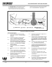
Figure 16
Venting System Termination Height
Note: The appliance and its individual shutoff
valve must be disconnected from the supply
piping system during any pressure testing of
that system at test pressures in excess of 1/2
psi (3.5 kPa). The appliance must be isolated
from the gas supply piping system by closing
the individual manual shutoff valve during any
pressure testing of the gas supply piping sys-
tem at test pressures equal to or less than 1/2
psi (3.5 kPa).
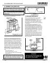
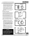
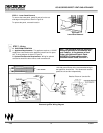
Figure 17
Gas Line
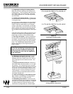
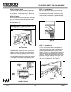
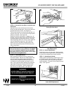
STEP 3 - Double Checking
When construction of the entire vent system has
been completed, double check to make sure all
venting sections and termination caps are unob-
structed. Exhaust gases are extremely hot.
When you have chosen a horizontal termination,
be sure there are no possible future obstructions
from trees, bushes, snow drifts, etc. A cap shield
can be purchased to help prevent possible con-
tact.
STEP 4- Gas line installation
Install the gas line piping up to the right side of
the appliance. A separate shut-off gas valve
(supplied) should always be used. See Figure 17.
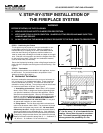
Roof Pitch H (Min.) Ft.
Flat to 6/12 ...........................................1.0
6/12 to 7/12 ..........................................1.25
Over 7/12 to 8/12..................................1.5
Over 8/12 to 9/12..................................2.0
Over 9/12 to 10/12................................2.5
Over 10/12 to 11/12..............................3.25
Over 11/12 to 12/12..............................4.0
Over 12/12 to 14/12..............................5.0
Over 14/12 to 16/12..............................6.0
Over 16/12 to 18/12..............................7.0
Over 18/12 to 20/12..............................7.5
Over 20/12 to 21/12..............................8.0
These termination heights are necessary in the
interest of safety and do not ensure draft-free
operation. Trees, buildings, adjoining roof lines,
adverse wind conditions, etc., may create a need
for a taller venting system termination should
down drafting occur.
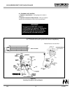
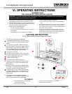
STEP 5 - Gas Line Connection
Gas connections can be made from within the appli-
ance by removing the lower panel. Connect the gas
line to the appliance manual valve inlet, using 1/2"
pipe. To ease installation, a listed flexible connector
and manual shut-off valve are supplied. The manual
shut-off valve should be connected directly to the
pipe, within the fireplace control area. All connec-
tions must be checked for leaks with a soap and
water solution or a leak detector.
Bleed the gas line to extract any air that may have
been trapped inside the pipe.
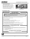
WARNING!
ALTHOUGH EACH UNIT IS LEAK TESTED
IN THE FACTORY, IT IS MANDATORY FOR
YOU TO CHECK FOR LEAKS DURING THE
FIRST BURN, DUE TO HANDLING THAT IS
BEY0ND THE CONTROL OF HEATILATOR
DUE TO SHIPPING, INSTALLATION , AND
THE LIKE. EVERY JOINT INCLUDING THE
VALVE, PILOT, FITTINGS, ETC., MUST BE
CHECKED TO ENSURE NO LEAKS HAVE
OCCURRED.