


12-98 7 21322K
GC150 SERIES DIRECT VENT GAS APPLIANCE
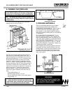
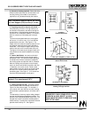
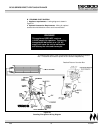
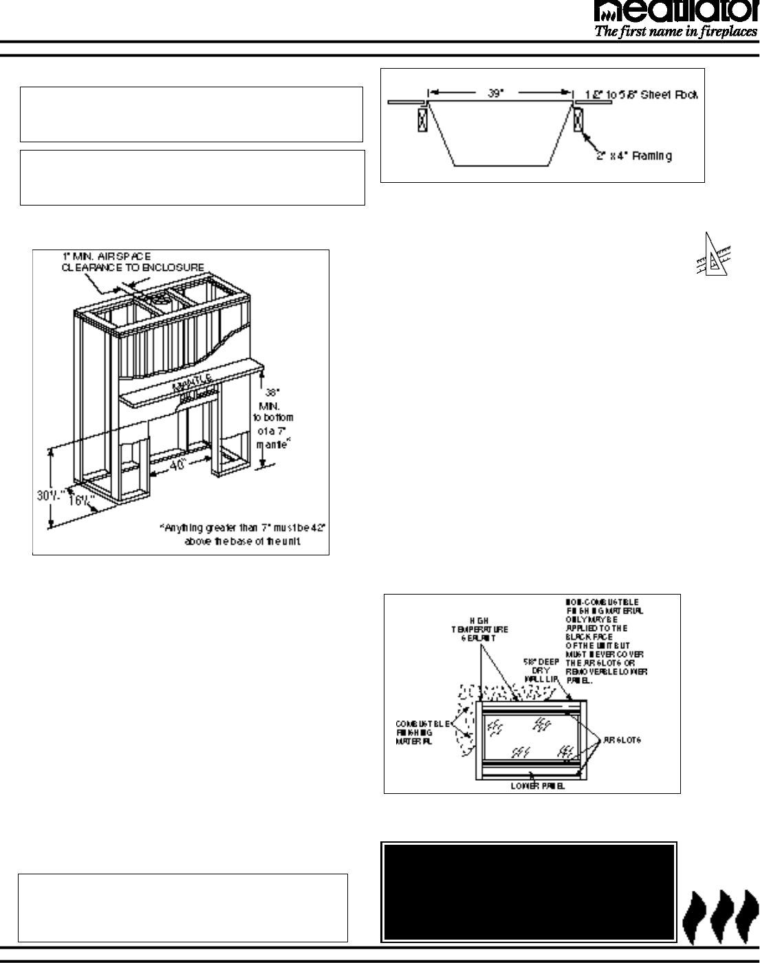
E. FRAMING THE FIREPLACE
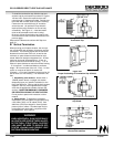
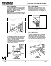
F. FINISHING MATERIALS
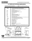
The GC150 Series Gas Appliance will fit a framed
opening of 40" w X 16
1
⁄2" d X 30
1
⁄8" h.
Only non-combustible materials may be used to
cover the black surfaces of the fireplace front.
Combustible Finishing Material. Material made of
or surfaced with wood, compressed paper, plant
fibers, plastics, or any material capable of igniting
and burning, whether flame proofed or not, plastered
or unplastered.
Non-combustible Finishing Material. Material
which will not ignite and burn. Such materials are
those consisting entirely of steel, iron, brick, tile, con-
crete, slate, glass or plasters, or combination thereof.
High Temperature Sealant Material. Sealants that
will withstand high temperatures (300° F+); General
Electric RTV103 (Black), or equivalent. Rutland, Inc.
Fireplace Mortar #63, or equivalent.
After completing the framing and applying the finish-
ing material (dry wall) over the framing, a non-com-
bustible sealant, one-half inch wide maximum, must
be used to close off any gaps at the top and sides
between the fireplace and facing to prevent cold air
leaks. See Figure 3.
Figure 2 - Framing the Fireplace
WARNING!
AIR SLOTS ON THIS APPLIANCE CAN-
NOT, IN ANY WAY, BE COVERED AS IT
MAY CREATE A FIRE HAZARD.
Figure 3
Finishing Materials
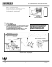
Note: If an optional fan (FK4) or hand held remote
control (RC4 or RC5) are to be used, wiring must
be done prior to finishing to avoid reconstruction.
Note: The remote wall switch must be wired prior
to applying the finishing material in order to avoid
reconstruction.
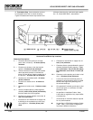
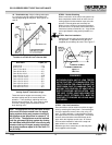
Figures 2 and 2a show a typical framing of this fire-
place assuming combustible materials are used. All
required clearances to combustibles around the fire-
place must be adhered to. A 1/2" air clearance must
be maintained at the back and sides of the firebox
assembly. A minimum of 38” is required to the bot-
tom of a 7” mantle. Anything greater than 7” must be
42” above the base of the unit. Any framing on top of
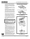
the fireplace must be above the top standoffs. Vent
sections for a horizontal run require a 3" minimum air
space on top and a 1" minimum air space on the
sides and bottom. Vertical rise sections require a 1"
minimum air space completely around the vent sec-
tions.
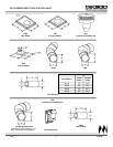
Flue outside diameter: 8"
Minimum firestop framing: 10" X10"
Face of header to the center of the firestop spacer
(FS6) framing: 8
7
/
8"
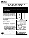
Note: The outside walls of the home around the
fire place should be insulated and finished as
one would any other outside wall, while maintain-
ing the 1/2"air clearance around the firebox.
Figure 2a
Framing the Fireplace