


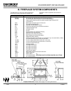
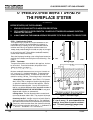
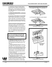
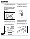
Figure 14
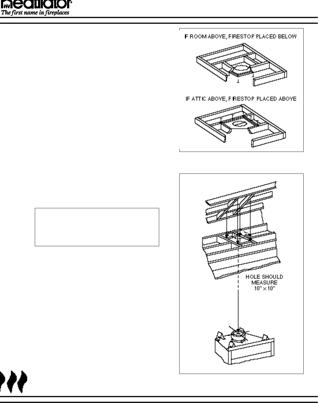
Ceiling and attic construction
12-98 12 21322K
GC150 SERIES DIRECT VENT GAS APPLIANCE
2. Preparing the ceiling for firestop spacers.
Mark and cut out an opening in the ceiling for the
firestop spacer. Frame the opening with the same
size lumber used in the ceiling joists. Unless the
flue if offset, frame the 10" x 10" opening directly
over the firebox.
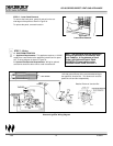
3. Installing the firestop spacers. Firestop spac-
ers must be used whenever the venting penetrates
a ceiling/floor area.
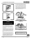
In all situations, firestop spacers are to be nailed to
the ceiling joists from the bottom or fireplace side,
EXCEPT when the space above is an insulated
ceiling or attic space. In this situation, the firestop
spacer must be nailed from the top side to prevent
loose insulation from falling into the required one
inch air space around the vent system. See Figure
13.
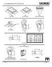
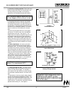
Install the firestop spacer (FS6) by positioning and
nailing the four sides of the firestop spacer to the
joists using a minimum of three nails per side.
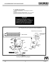
4. Securing vent system. Continue assembling
the vent sections up through the firestop spacers
as needed. vent sections must be locked into posi-
tion with the screws provided, using the predrilled
holes. The 15942B starter elbow and the vent sta-
bilizers have straps for securing these parts to
joists or rafters.
Note: Be sure to provide intermediate sup-
port for the vent during construction and
check to be sure inadvertent loading has
not dislodged the vent from the appliance
or any vent joint.
Figure 13
Installing the firestop spacer
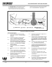
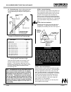
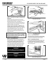
6. Marking the exit point in the roof. L o c a t e
the point where the venting will exit the roof by
plumbing down to the center of the vent. Drive a
nail up through the roof to mark the center. See
Figure 15.
7. Cutting out the hole in the roof. Measure to
either side of the nail and mark the 10" x 10" open-
ing required. This is measured on the horizontal;
actual length may be larger depending on the pitch
of the roof. Cut out and frame the opening. See
chapter 25 of the Uniform Building Code for Roof
Framing details. A one inch minimum air space
clearance must be maintained between the chim-
ney section and the roof.
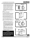
8. Install roof flashing or site-produced chase
top. Position a roof flashing or a site-produced
chase top and secure in place with nails.
9. Assembling vent sections. Continue to add
vent sections through the roof opening, maintaining
at least a one inch air space clearance. If a specif-
ic height is desired, the chimney sections may
have to be cut (using shears) to a certain length.