


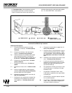
12-98 10 21322K
GC150 SERIES DIRECT VENT GAS APPLIANCE
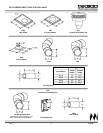
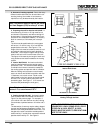
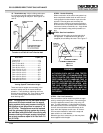
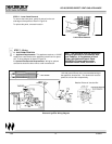
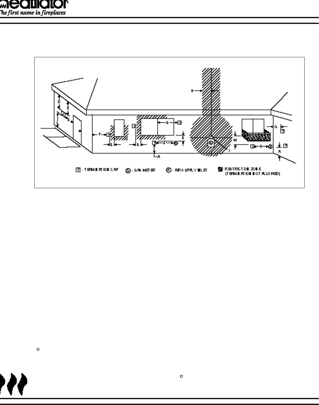
Figure 9
Horizontal Termination Cap Locations
Dimension Descriptions
A = Clearance above the ground, a veranda,
porch, deck, or balcony - 12 inches (30 cm)
minimum.
B = Clearance to window or door that may be
opened - 9 inches (30 cm) minimum.
D
*
= Vertical clearance to ventilated soffit located
above the terminal within a horizontal dis-
tance of 2 feet (60 cm) from the center-line of
the terminal - 18 inches (46 cm) minimum.
E
*
= Clearance to unventilated soffit - 12 inches
(30 cm) minimum.
F = Clearance to outside corner - 9 inches as
tested.
G = Clearance to inside corner - 9 inches as test-
ed.
H• = Not to be installed above a meter/regulator
assembly within 3 feet (90 cm) horizontally
from the center-line of the regulator.
I = Clearance to service regulator vent outlet - 6
feet (1.8 m) minimum.
J = Clearance to non-mechanical air supply inlet
to building or the combustion air inlet to any
other appliance - 12 inches (30 cm) mini-
mum.
K• = Clearance to mechanical air supply inlet - 6
feet (1.8 m) minimum.
L+ = Clearance above a paved sidewalk or paved
driveway located on public property - 7 feet
(2.1 m) minimum. Use of a CS will reduce
this dimension to as low as 12 inches (30
cm).
M# = Clearance under veranda, porch deck, or bal-
cony - 12 inches (30 cm) minimum.
+ A vent must not terminate directly above a
sidewalk or paved driveway which is located
between two single family dwellings and
serves both dwellings.
# Only permitted if veranda, porch deck, or bal-
cony is fully open on a minimum of 2 sides
beneath the floor.
•
As specified in Installation Codes. Note:
Local codes or regulations may require differ-
ent clearances.
*
30 inches/76 cm minimum distance required
for vinyl soffit materials.
As specified in CGA B149 Installation Codes
(1991). Note: Local Codes or Regulations
may require different clearances.
5. Termination Cap. Vent termination must not
be recessed into the wall or exterior sheeting.
Figure 9 illustrates termination cap locations and
minimum dimensions for each termination applica-
tion. Or, follow ANSI Z223.1, latest edition.