


4-99 14 21322M
GC150 SERIES DIRECT VENT GAS APPLIANCE
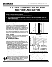
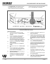
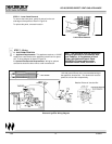
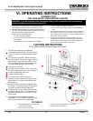
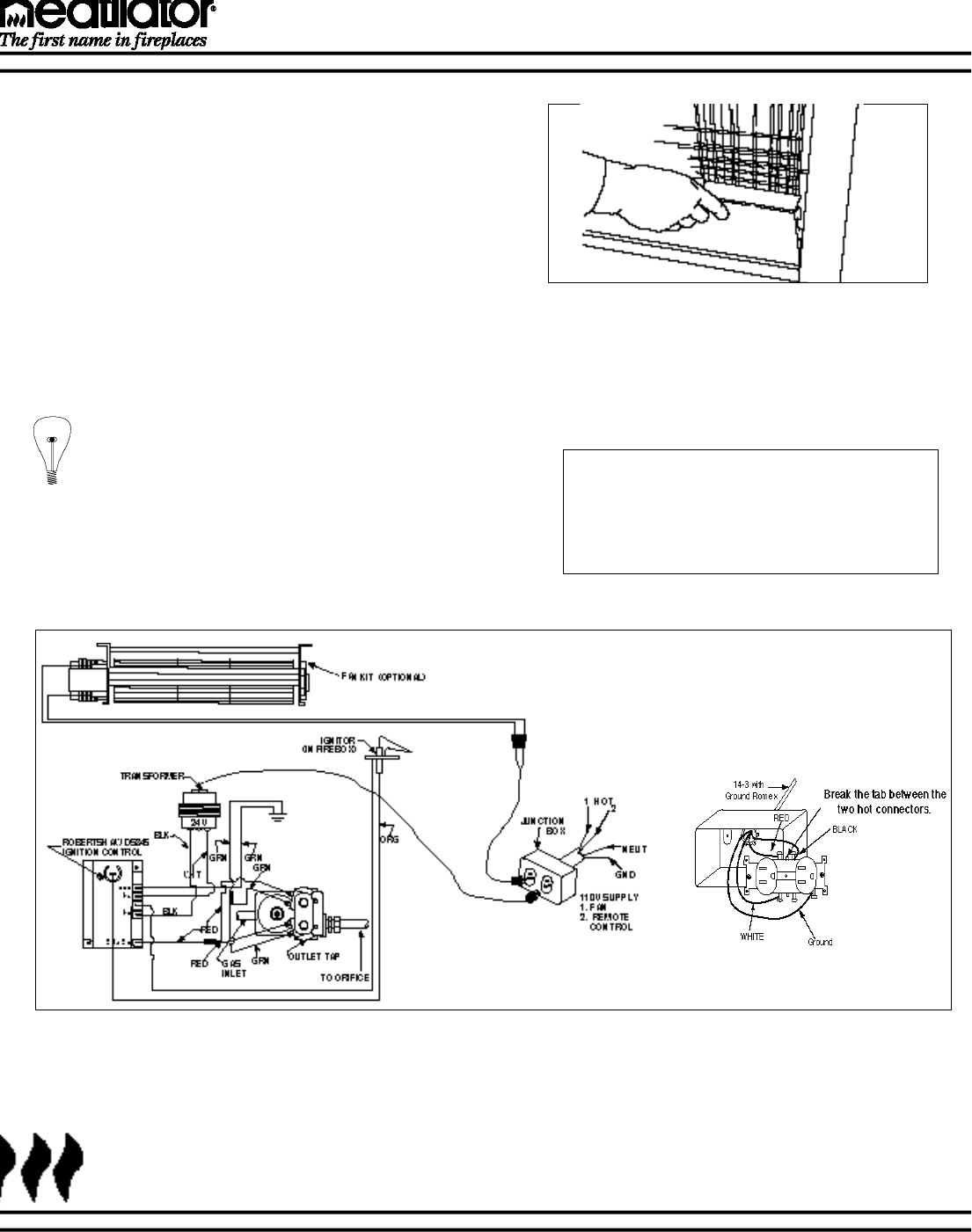
Figure 19
Electronic Ignition Wiring Diagram
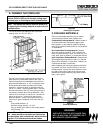
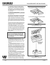
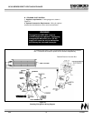
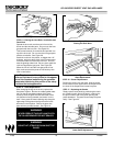
STEP 6 - Lower Panel Removal
To remove the lower panel, gently lift and pull on the out-
side edges of the panel as shown in Figure 18.
To replace the panel, reverse this action.
Figure 18
Lower Panel Removal
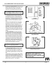
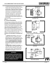
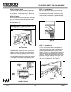
14-3 with ground Romex is the recommended wiring to
the appliance Junction Box. This allows each outlet to
power the unit and fan independently.
Detailed Picture of Junction Box
A. ELECTRONIC IGNITION
1. Appliance Requirements. This appliance requires a 110VAC
supply from a wall switch to the appliance junction box for opera-
tion. A wiring diagram is shown in Figure 19.
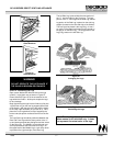
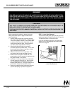
2. Optional Accessories Requirements. Wiring for optional
accessories should be done now to avoid reconstruction.
Note: This appliance must be electrically
wired and grounded in accordance with
local Codes or, in the absence of local
Codes, with National Electric Code
ANSI/NFPA 70-latest edition or the
Canadian Electric Code, CSA C22.1.
STEP 7 - Wiring