


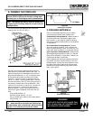
STEP 1 - Positioning the Firebox
This fireplace may be placed on a smooth combustible or non-
combustible continuous, flat surface. When the appliance is
installed directly on carpeting, tile or other combustible material
other than wood flooring, the appliance shall be installed on a
metal or wood panel extending the full width and depth of the appli-
ance.
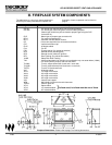
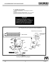
Slide the unit into position and level the fireplace from side-
to-side and front-to-back. Shim with non-combustible material,
such as sheet metal, as necessary.
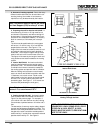
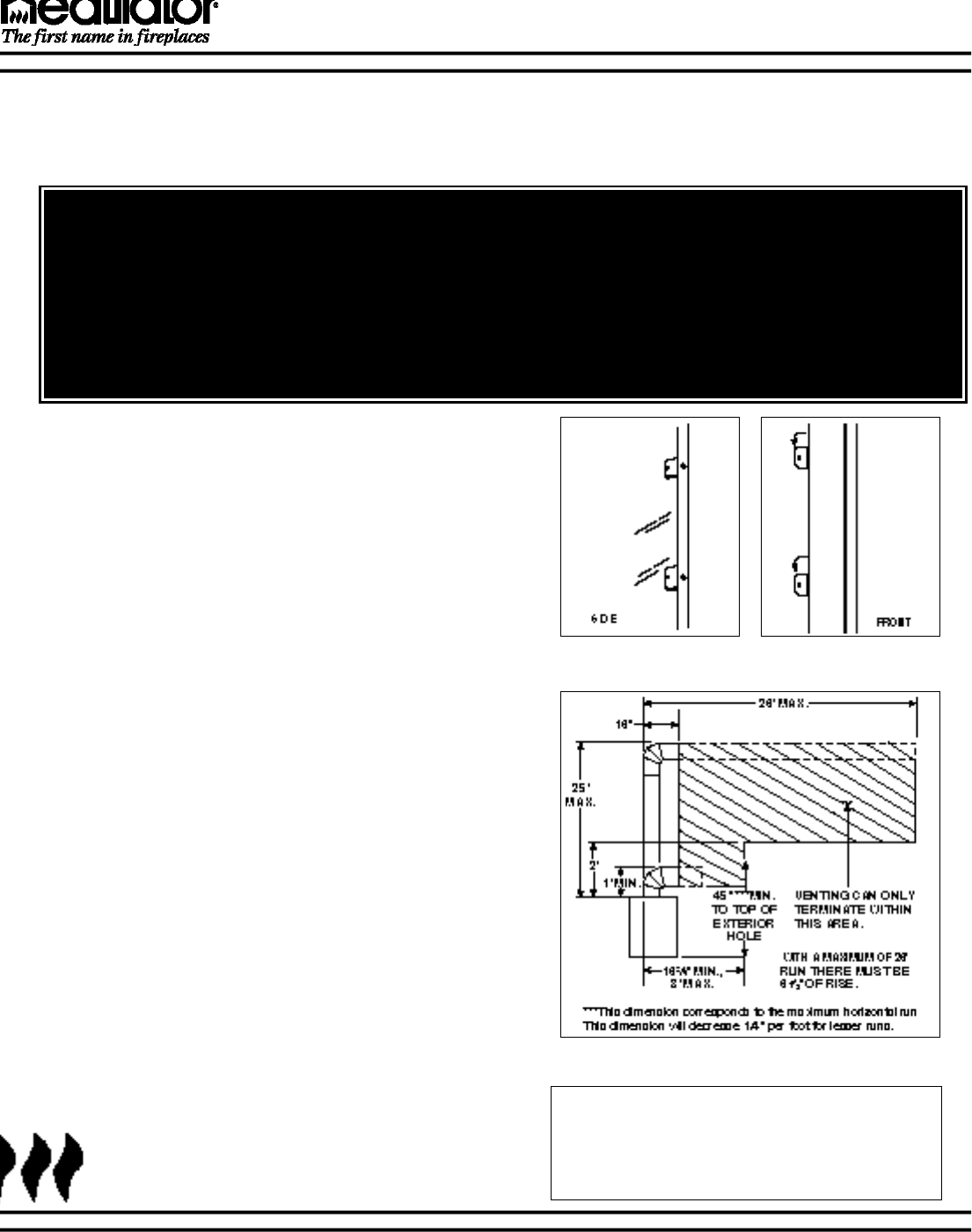
Secure the fireplace by bending out the nailing flanges located on
each side of the fireplace and nailing the unit to the framing. See
Figure 4.
STEP 2 - Termination
Two types of termination are available for this appliance, horizon-
tal and vertical. For vertical termination, skip section A and
advance to section B on page 11.
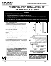
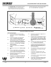
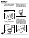
A. Horizontal Termination
Minimum combustible clearances to the vent on a horizontal run
is 3" on top and 1" on the bottom and sides. These clearances
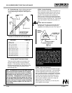
must be maintained at all times. The maximum horizontal run
allowed for venting is 26 feet. The maximum vertical rise allowed
for horizontal termination is 25 feet. See Figure 5.
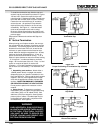
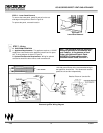
1. Assembling vent sections. Attach either a VE12 (starter
elbow), VE16, VE20 or straight vent section (depending upon
your specific installation) to the top of the appliance. Secure
with the three screws supplied. Use only vent supplied and
listed for use with this appliance and the appropriate number of
direct vent sections. MAINTAIN MINIMUM CLEARANCES
OR GREATER AROUND THE VENT SYSTEM. Do not pack
air spaces with insulation or other material.
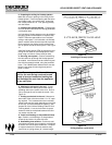
a. Using elbows. The first elbow used with horizontal termi-
nation must be starter elbow 15942. The maximum horizontal
distance this vent system may reach is 26'. No more than 3
elbows may be used. A single vertical-to-horizontal elbow is
already calculated into the allowable 26' run. Each additional
elbow reduces the maximum horizontal distance by three feet.
Example, by using three total elbows, the maximum horizontal
distance has been reduced to twenty feet (3 - 1 = 2 elbows X 3'
= 6'; 26' max. - 6' of elbows = 20' of horizontal run).
Figure 5 - Horizontal Length
Figure 4
Nailing Flanges
1-99 8 21322L
GC150 SERIES DIRECT VENT GAS APPLIANCE
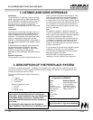
V. STEP-BY-STEP INSTALLATION OF
THE FIREPLACE SYSTEM
WARNING!
BEFORE STARTING, DO THE FOLLOWING:
1. WEAR GLOVES AND SAFETY GLASSES FOR PROTECTION.
2. KEEP HAND TOOLS IN GOOD CONDITION. SHARPEN CUTTING EDGES AND MAKE SURE TOOL
HANDLES ARE SECURE.
3. ALWAYS MAINTAIN THE MINIMUM AIR SPACE REQUIRED TO THE ENCLOSURE TO PREVENT FIRE.
A B
Note: The horizontal run of vent must have a
1/4" rise for every 1 ft. of run towards the ter-
mination. Never allow the vent to run down-
ward. This could cause high temperatures
and may present the possibility of a fire.