


9Heat & Glo • XLR-N-AU, XLR-PB-AU • 2198-906 Rev. M • 5/12
A. ApplianceCertication
NOTINTENDEDFORUSEASAPRIMARYHEATSOURCE.
This appliance is tested and approved as either supplemen-
tal room heat or as a decorative appliance. It should not be
factored as primary heat in residential heating calculations.
C. HighAltitudeInstallations
NOTICE: If the heating value of the gas has been reduced,
these rules do not apply. Check with your local gas utility
or authorities having jurisdiction.
When installing above 2001 ft. (610 m) elevation:
Reduce input rate 4% for each 1001 ft. (305 m) above
2001 ft. (610 meters).
D. Non-CombustibleMaterialsSpecication
Material which will not ignite and burn. Such materials are
those consisting entirely of steel, iron, brick, tile, concrete,
slate, glass or plasters, or any combination thereof.
Materials that are reported as passing ASTM E 136,
StandardTestMethodforBehaviorofMaterialsina
Vertical Tube Furnace at 750ºC and UL763shall be
considered non-combustible materials.
E. CombustibleMaterialsSpecication
Materials made of or surfaced with wood, compressed pa-
per, plant bers, plastics, or other material that can ignite
and burn, whether ame proofed or not, or plastered or
unplastered shall be considered combustible materials.
F. ElectricalCodes
All electrical safety testing has been done following the EN
60335-2-102 standard. Local codes apply.
1
ListingandCodeApprovals
MODELS: XLR-N-AU,XLR-PB-AU
LABORATORY: SAIGlobal
TYPE: DecorativeFuelEffectAppliances
STANDARD:AS4558:2000
The Heat & Glo gas appliances discussed in this Installer’s
Guide have been tested to certication standards and listed
by the applicable laboratories.
This appliance must be installed in accordance with the
rules in force.
NOX Class 5 for G20, NOX Class 5 for G31
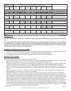
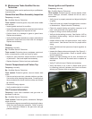
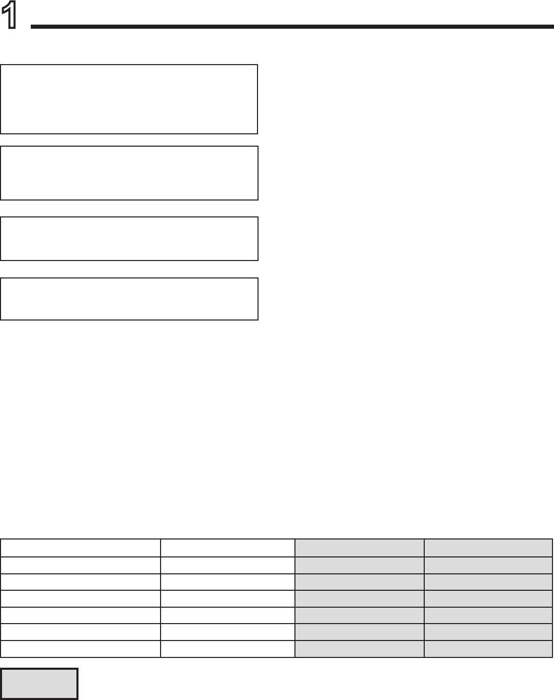
B. GasPressureRequirements
Pressure requirements for XLR replaces are shown in
table below.
Two taps are provided on the right hand side of the gas
control for a test gauge connection to measure the inlet
and outlet pressures.
The replace and its individual shut-off valve must be dis-
connected from the gas supply piping system during any
pressure testing of the system at test pressures in excess
of 60 mbar.
If the replace must be isolated from the gas supply pip-
ing system by closing an individual shut-off valve, it must
be of the handle-less type.
NaturalGas Propane Butane
Inlet Gas Pressure 1.13 - 3.40 kPa 2.75 - 3.40 kPa 2.75 - 3.40 kPa
Outlet (Manifold) Gas Pressure .80 - .95 kPa 2.36 - 2.61 kPa 2.36 - 2.61 kPa
Gas Rate .405
m3
/
h
.134
m3
/
h
.111
m3
/
h
Maximum Gas Consumption 26 MJ/h 26.0 MJ/h 22 MJ/h
Burner Injector DMS 42 (2.350 mm) DMS .057 (1.450 mm) DMS 55 (1.325)
Pilot Injector 51 30 30
Columns highlighted in gray = The gas control valve supplied with this product is approved for a maximum
inlet pressure of 3.40kPa. For pressures over 3.40kPa, an in line pressure regulator must be installed
upstream from the gas control valve.