


47Heat & Glo • XLR-N-AU, XLR-PB-AU • 2198-906 Rev. M • 5/12
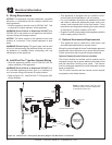
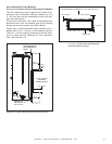
WARNING! Risk of Fire! Maintainspeciedairspace
clearancestocombustibles.
Failure to comply with these instructions may cause a
re or cause the appliance to overheat.
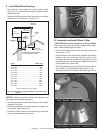
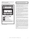
LOWER COVER PANEL
TOP FLANGE
FINISHING FLANGES
SIDE COLUMNS
= NO SCREWS ALLOWED
= 1 in. (25 mm) MAX. SELF-TAPPING
SCREWS ALLOWED
= 5 in. - 7 in. (130 mm - 180 mm)
SELF-TAPPING SCREWS ALLOWED
FACTORY-INSTALLED
NON-COMBUSTIBLE BOARD
Figure13.3FinishingDetails
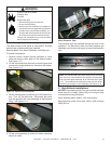
CAUTION! Risk of Glass Damage and Cuts! DO NOT
drill or install any type of screw or fastener into the lower
cover panel. Sharp screw or fastener tips may penetrate
and break the glass or cause cuts.
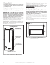
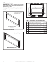
The XLR-AU must be nished using either the Tonic or
Martini decorative fronts. See Figures 13.16 and 13.17.
The nal replace installation can be accomplished by ei-
ther the Overlap Fit or Inside Fit method. Reference Sec-
tion 13.C regarding installation details associated with the
Inside Fit and Overlap Fit methods.
It is acceptable to pre-drill holes and use self-tapped
screws in the factory-installed non-combustible board to
attach non-combustible backer board for tile, marble, etc.
Refer to gure 13.3 for acceptable screw location and
screw length requirements.
Self-tapping screws up to 1 in. (25 mm) long can be in-
stalled through the nailing tab and outer 1-3/4 in. (45 mm)
edges of the factory-installed non-combustible board to
secure the drywall adjacent to the factory-installed non-
combustible board. See Figure 13.3.
Do not drill or install screws which may penetrate the low-
er cover panel as this will restrict required access to the
glass, battery-back-up, and remote receiver. See Figure
13.3.
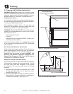
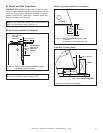
The appliance is designed to accept 1/2 (13 mm) wall
sheathing materials such as drywall, plywood, wood com-
posites, or non-combustible materials. The type of material
used depends whether the installation is an Inside or Over-
lap Fit Method. Refer to Section 13.C regarding installation
details associated with the Inside an Overlap Fit methods.
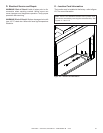
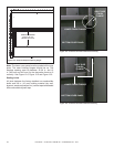
The left/right sides and bottom of the replace opening uti-
lize nishing anges that will overlap the 3/8 in. (10 mm)
wall sheathing. The 3/8 in. (10 mm) thick wall sheathing
can be installed tight to the left, right, and bottom nish-
ing anges such that the rough edges of the sheathing are
tucked behind the anges when using the Overlap Method
of nishing.
Note: Finishing materials are designed to overlap the outer
edges of the nishing anges up to the replace opening.
NOTE:Itisacceptabletouseahightemperaturesili-
conesealant (149°C(300°F)minimumcontinuousex-
posure) toadheredrywalltolowercoverpanel.
Note: Refer to Section 13.C regarding installation details as-
sociated with the Inside and Overlap Fit methods.