


27Heat & Glo • XLR-N-AU, XLR-PB-AU • 2198-906 Rev. M • 5/12
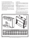
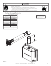
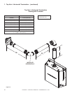
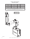
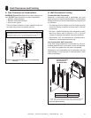
Figure7.5VerticalVentMaximum
Note: If installing a vertical vent/termination off the top of the
appliance, the optional exhaust restrictor may be needed.
V
1
V
1
Max=44ft.(13.4m)
TopVent-VerticalTermination
NoElbows
Note: Use SLP Series
components only.
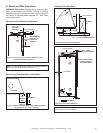
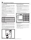
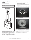
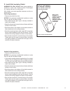
ExhaustrestrictorInstructions
1. Locate the two pilot holes located in the inside rebox
heat shield as shown in Figure 7.6.
2. Center the exhaust restrictor such that the through
holes in the vent restrictor align with the pilot holes in
the heat shield.
3. Use (2) 1/2 in. (13 mm) self-piercing screws to secure
vent restrictor to rebox heat shield. See Figure 7.7.
Exhaust restrictors are recommended for these vertically
terminated products which have excessive draft. Exhaust
restrictors will compensate for high draft. and restore vi-
sual ame height. If the vent conguration has a total ver-
tical of 15 ft. - 44 ft. (4.6 m - 13.4 m), an exhaust restrictor
may be needed. The exhaust restrictor can be located in
the appliance manual bag.
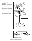
Figure7.7ExhaustRestrictorInstallation
Figure7.6LocationofPilotHoles
PILOTHOLES
NOTICE: Before painting, contact your dealer for informa-
tion on the appropriate high temperature paint.
4. In some applications, such as those where the re-
place is elevated off the oor, the vent restrictor may
be painted, but painting is not required.