


Heat & Glo • ESC-42ST • 2146-900 Rev. o • 5/1220
C
B
D
A
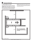
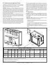
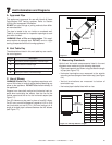
B. Constructing the Appliance Chase
A chase is a vertical box-like structure built to enclose the
gas appliance and/or its vent system. In cooler climates
the vent should be enclosed inside the chase.
NOTICE: Treatment of ceiling fi restops and wall shield
fi restops and construction of the chase may vary with the
type of building. These instructions are not substitutes
for the requirements of local building codes. Therefore,
you MUST check local building codes to determine the
requirements to these steps.
Chases should be constructed in the manner of all out-
side walls of the home to prevent cold air drafting prob-
lems. The chase should not break the outside building
envelope in any manner.
Walls, ceiling, base plate and cantilever fl oor of the chase
should be insulated. Vapor and air infi ltration barriers
should be installed in the chase as per regional codes for
the rest of the home. Additionally, in regions where cold
air infi ltration may be an issue, the inside surfaces may be
sheetrocked and taped for maximum air tightness.
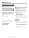
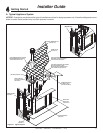
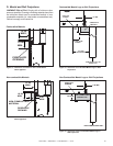
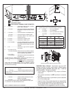
Figure 5.2 Clearances to Combustibles
C. Clearances
NOTICE: Install appliance on hard metal or wood surfaces
extending full width and depth. DO NOT install directly
on carpeting, vinyl, tile or any combustible material other
than wood.
WARNING! Risk of Fire! Maintain specifi ed air space
clearances to appliance and vent pipe:
• Insulation and other materials must be secured to prevent
accidental contact.
• The chase must be properly blocked to prevent blown
insulation or other combustibles from entering and
making contact with fi replace or chimney.
• Failure to maintain airspace may cause overheating and
a fi re.
To further prevent drafts, the wall shield and ceiling fi re-
stops should be caulked with caulk with a minimum of
300ºF continuous exposure rating to seal gaps. Gas line
holes and other openings should be caulked with caulk
with a minimum of 300ºF continuous exposure rating or
stuffed with unfaced insulation. If the appliance is being
installed on a cement surface, a layer of plywood may be
placed underneath to prevent conducting cold up into the
room.
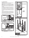
F
E=33 IN.
G
H
I
E=43 IN.
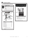
MINIMUM FRAMING DIMENSIONS*
A B** C* D E F** G** H I
Rough
Opening
(Vent Pipe)
Rough
Opening
(Height)
Rough
Opening
(Depth)
Rough
Opening
(Width)
Clearance
to ceiling
from opening
Clearance
to ceiling
from top of
appliance
Combustible
Floor
Combustible
Flooring
Sides of
Appliance
Front of
Appliance
Inches 10 46-1/2 30 60-1/4 43 33 0 See Note Below 1 36
Millime-
ters
254 1181 762 1530 1092 838 0 See Note Below 25 914
* Adjust framing dimensions for interior sheathing (such as sheetrock)
** Fireplace may need to be elevated from the fl oor affecting framing height B, depending on hearth construction. See Section 5.E
for hearth and combustible fl oor requirements.