


Heat & Glo • 6000GCF-IPI, 6000GCF-IPILP • 2110-900 Rev. F • 6/08 39
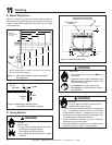
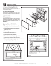
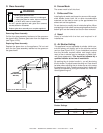
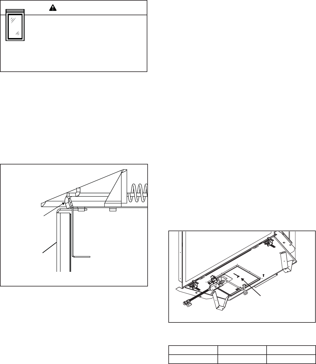
Figure 12.20 Glass Assembly
G. Glass Assembly
Removing Glass Assembly
Pull the four glass assembly latches out of the groove on
the glass frame. Remove glass door from the appliance
(see Figure 12.20).
Replacing Glass Assembly
Replace the glass door on the appliance. Pull out and
latch the four glass assembly latches into the groove on
the glass frame.
Handle glass doors with care.
• Inspect the gasket to ensure it is undamaged.
• Inspect the glass for cracks, chips or scratches.
• Do NOT strike, slam or scratch glass.
• Do NOT operate appliance with glass door removed,
cracked, broken or scratched.
• Replace glass door assembly as a complete appliance.
H. Screen Mesh
The screen mesh is built into front.
I. Grilles and Trim
Install optional marble and brass trim surround kits as de-
sired. Marble, brass, brick, tile, or other noncombustible
materials can be used to cover up the gap between the
sheet rock and the appliance.
Do not obstruct or modify the air inlet/outlet grilles. When
overlapping on both sides, leave enough space so that the
bottom grille can be lowered and the trim door removed.
LATCHES
(BOTH BOTTOM
AND TOP)
GLASS
ASSEMBLY
J. Hood
Hood is included with the front and required in all
installations.
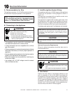
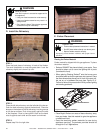
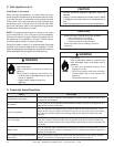
K. Air Shutter Setting
This appliance has an adjustable air shutter (which con-
trols the primary air) factory set for the minimum vertical
vent run (see Figure 12.21). If your installation has more
than the minimum required vertical vent length, adjust-
ment of the air shutter may be necessary to obtain opti-
mal fl ame appearance. This should be adjusted by a
qualifi ed installer at the time of installation.
By pushing the air shutter handle in, you will be closing
the air shutter. To adjust loosen the wing nut. Care should
be taken when adjusting the air shutter so as not to cause
the appliance to soot. If sooting occurs the air shutter will
need to be opened by pulling the handle out. When fi n-
ished tighten wing nut.
Figure 12.21
Shutter Settings
NG LP
Burner 1/8 in. Full Open
WARNING
AIR SHUTTER
WING NUT