


Heat & Glo • 6000GCF-IPI, 6000GCF-IPILP • 2110-900 Rev. F • 6/08 11
V
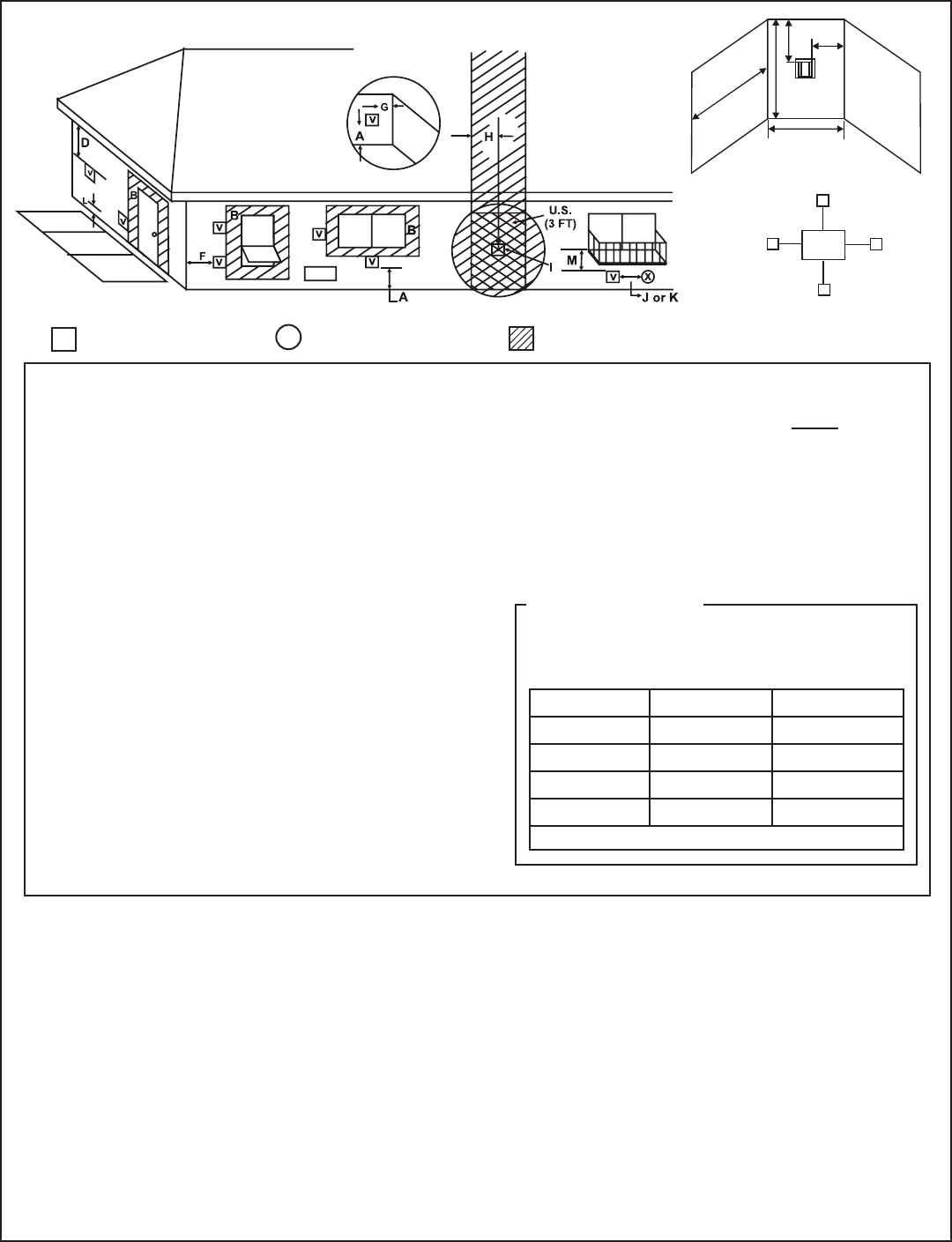
= VENT TERMINAL
X
= AIR SUPPLY INLET
= AREA WHERE TERMINAL IS NOT PERMITTED
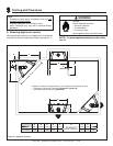
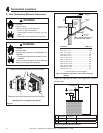
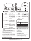
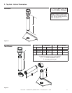
Figure 4.4 Minimum Clearances for Termination
A = 12 inches.................clearances above grade, veranda,
porch, deck or balcony
B = 12 inches.................clearances to window or door
that may be opened, or to perma-
nently closed window. (Glass)
D* = 18 inches.................vertical clearance to unventilated
soffi t or to ventilated soffi t located
above the terminal
*30 inches ................for vinyl clad soffi ts and below
electrical service
F = 9 inches..................clearance to outside corner
G = 6 inches...................clearance to inside corner
H = 3 ft. (Canada) ..........not to be installed above a gas
meter/regulator assembly within 3
feet (90 cm) horizontally from the
center-line of the regulator
I = 3 ft ...........................clearance to gas service regulator
vent outlet
J = 9 inches (U.S.A.)
12 inches (Canada) clearance to non-mechanical
air supply inlet to building or the
combustion air inlet to any other
appliance
K = 3 ft. (U.S.A.)
6 ft. (Canada) ...........clearance to a mechanical (pow-
ered) air supply inlet
CAUTION: IF EXTERIOR WALLS ARE FINISHED WITH VINYL SIDING, IT IS SUGGESTED THAT A VINYL PROTECTOR KIT BE INSTALLED.
** a vent shall not terminate directly above a sidewalk or paved driveway
which is located between two single family dwellings and serves both
dwellings.
*** only permitted if veranda, porch, deck or balcony is fully open on a
minimum of 2 sides beneath the fl oor, or meets Note 2.
NOTE 1: On private property where termination is less than 7 feet above
a sidewalk, driveway, deck, porch, veranda or balcony, use of a listed cap
shield is suggested. (See vents components page)
NOTE 2: Termination in an alcove space (spaces open only on one side
and with an overhang) are permitted with the dimensions specifi ed for
vinyl or non-vinyl siding and soffi ts. 1. There must be 3 feet minimum
between termination caps. 2. All mechanical air intakes within 10 feet
of a termination cap must be a minimum of 3 feet below the termination
cap. 3. All gravity air intakes within 3 feet of a termination cap must be a
minimum of 1 foot below the termination cap.
(See Note 1)
(See Note 2)
NOTE 3: Local codes or regulations may require different
clearances.
NOTE 4: Termination caps may be hot. Consider their proximity to
doors or other traffi c areas.
NOTE 5: Location of the vent termination must not interfere with
access to the electrical service.
WARNING: In the U.S: Vent system termination is NOT permitted in
screened porches. You must follow side wall, overhang and ground
clearances as stated in the instructions.
In Canada: Vent system termination is NOT permitted in screened
porches. Vent system termination is permitted in porch areas with
two or more sides open. You must follow all side walls, overhang
and ground clearances as stated in the instructions.
Heat & Glo assumes no responsibility for the improper performance
of the appliance when the venting system does not meet these
requirements.
Electrical
Service
V
S
V
S
V
T
D*
V
M
N
P
R
Q
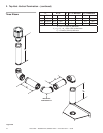
N = 6 inches ..................non-vinyl sidewalls
12 inches ................vinyl sidewalls
P = 8 ft.
Q
MIN
R
MAX
1 cap 3 feet 2 x Q
ACTUAL
2 caps 6 feet 1 x Q
ACTUAL
3 caps 9 feet 2/3 x Q
ACTUAL
4 caps 12 feet 1/2 x Q
ACTUAL
Q
MIN
= # termination caps x 3 R
MAX
= (2 / # termination caps) x Q
ACTUAL
Alcove Applications
(See Note 1)
(See Note 5)
(See Note 5)
L** = 7 ft. ......................... clearance above paved
sidewalk or a paved driveway
located on public property
M*** = 18 inches................ clearance under veranda, porch,
deck, balcony or overhang
42 inches ............... vinyl
S = 6 inches................. clearance from sides of electri-
cal service
T = 12 inches................ clearance above electrical
service