


Heat & Glo • 6000GCF-IPI, 6000GCF-IPILP • 2110-900 Rev. F • 6/08 17
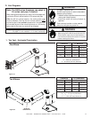
A. Pipe Clearances to Combustibles
6
6
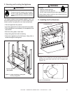
Vent Clearances and Framing
Fire Risk.
Explosion Risk.
Maintain vent clearance to combustibles as
specifi ed.
• Do not pack air space with insulation or
other materials.
Failure to keep insulation or other materials
away from vent pipe may cause fi re.
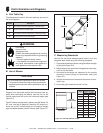
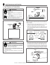
Figure 6.1 Pipe Clearances
1 in. CLEARANCE
AROUND VERTICAL
SECTIONS
3 in. TOP
CLEARANCE
1 in. SIDE AND
BOTTOM CLEARANCE
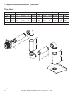
WARNING
COMBUSTIBLE SURFACE
DIRECTION
UP
HEAT SHIELD
90º ELBOW
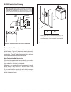
Figure 6.2
Figure 6.3
CORRECT INCORRECT
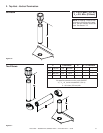
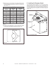
Fasten the shield in place using the four pilot holes pro-
vided in the part.
• Position the shield so the longest dimension (13 1/2 inch)
is placed in same direction the elbow is pointing.
• Center the shield directly above the elbow with a 1/2
inch air space between shield and combustible surface
(see Figure 6.3).
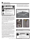
HEAT
SHIELD
3 IN MIN.
(76 mm)
COMBUSTIBLE
SURFACE
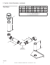
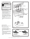
WARNING
Fire Risk.
Installation of this appliance may require the
use of heat shield 385-920 above the fi rst 90º
elbow in the venting system.
• Heat shield required if vertical distance between top of
horizontal elbow and any combustible surface above elbow
is less than 4 inches.
• Heat shield not required if distance is more than 4
inches.
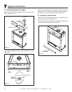
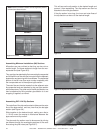
• Attach elbow heat shield to the exhaust pipe if combusti-
ble materials are not present at install (see Figure 6.4).
• Cut the tabs as shown and bend down. Using the screws
found in the manual bag secure the heat shield to the pipe
maintaining 3 to 4 inches between the pipe and shield.
SCREW
3 in.
(76 mm)
Figure 6.4