


Heat & Glo • 6000GCF-IPI, 6000GCF-IPILP • 2110-900 Rev. F • 6/08 23
Fire Risk
Exhaust Fumes Risk
Impaired Performance of Appliance
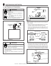
• Overlap pipe slip sections at least 1-1/2
inches.
• Use pilot holes for screws.
• Screws must not exceed one inch long.
• Pipe may separate if not properly joined.
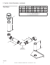
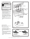
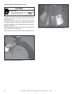
A. Assembly of Vent Sections
8
8
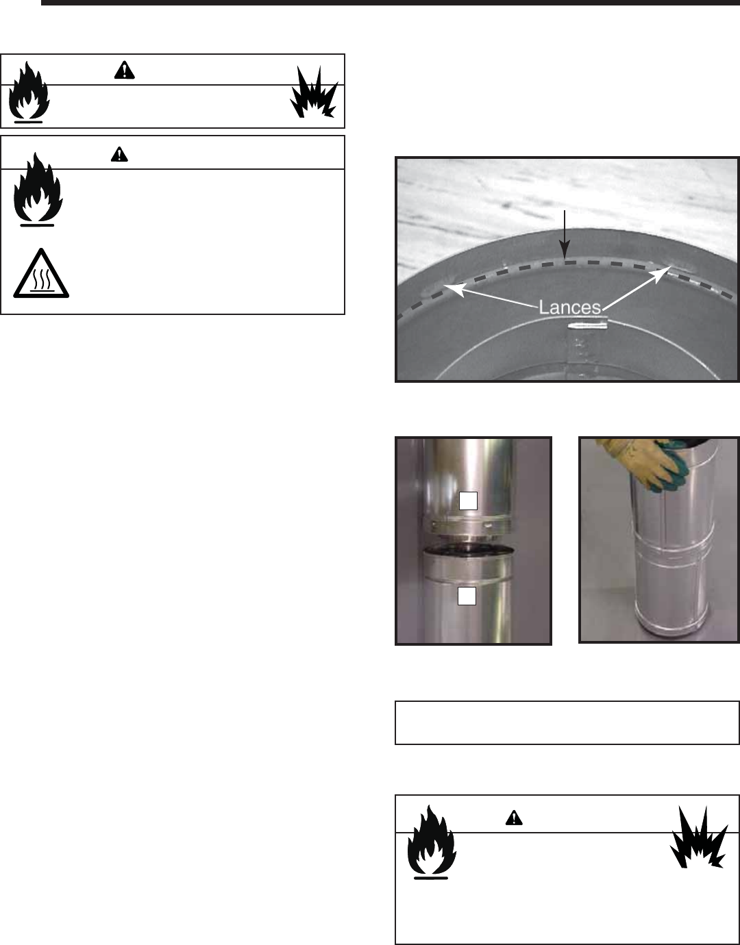
Installing Vent Pipe
Assembling Pipe Sections
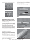
Insert the inner fl ue of section A into the fl ared inner fl ue of
section B.
Start the outer fl ue of section A over the outer fl ue of section
B (see Figure 8.2). Note: The end of the pipe sections with
the lances/tabs on it will face towards the appliance.
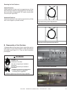
Once both inner and outer fl ues are started, press section
A onto section B fi rmly until all lances have snapped into
place. Check to make sure they have snapped together
(see Figure 8.3) and the seams are not aligned (see Fig-
ure 8.4). Tug slightly on section A to confi rm it has com-
pletely locked into place. It is acceptable to use screws no
longer than 1 inch to hold outer pipe sections together. If
predrilling holes, do NOT penetrate inner pipe.
For 90° and 45° elbows that are changing the vent direction
from horizontal to vertical, one screw minimum should be
put in the outer fl ue at the horizontal elbow joint to prevent
the elbow from rotating. Use screws no longer than 1 inch.
If predrilling screw holes, do NOT penetrate inner pipe.
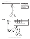
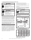
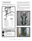
Attaching Vent to the Firebox Assembly
To attach the fi rst pipe section to the collars, slide the male
end of the inner vent of the pipe section over the inner collar
on the fi rebox assembly. At the same time, slide the outer
fl ue over the outer collar on the appliance. Push the pipe
section into the appliance collar until all the lances (see
Figure 8.1) have snapped in place. Tug slightly on the sec-
tion to confi rm it has completely locked into place.
Figure 8.1 Lances
Figure 8.2
A
B
Figure 8.3
WARNING
Commercial, Multi-family (Multi-level exceeding two
stories), & High-Rise Applications
For Installation into Commercial, multi-family (multi-level ex-
ceeding two stories) or high-rise applications: All pipe joints
must be sealed with high temperature silicone, including the
slip section that connects directly to the horizontal termina-
tion cap.
Fire Risk
Explosion Risk
If slip section seals are broken during the
removal of the termination cap, gas will leak and
a fi re or explosion may occur.
Do not break silicone seals on slip sections.
WARNING
Note: The end of the pipe sections with the lances/tabs on
it will face toward the appliance.
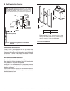
High Temperature Silicone Sealant
Commercial, Multi-family (multi-level exceeding two
stories), or High-rise Applications only
• Apply a bead of silicone sealant inside the female outer
pipe joint prior to joining sections. See Figure 8.1
• Only outer pipes are sealed. Do not seal the inner fl ue.
All unit collar, pipe, slip section, elbow and cap outer fl ues
shall be sealed in this manner, unless otherwise stated.
Do not mix pipe, fi ttings or joining
methods from different manufacturers.
WARNING