


Heat & Glo • 6000GCF-IPI, 6000GCF-IPILP • 2110-900 Rev. F • 6/0834
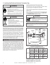
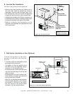
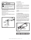
A. Mantel Projections
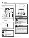
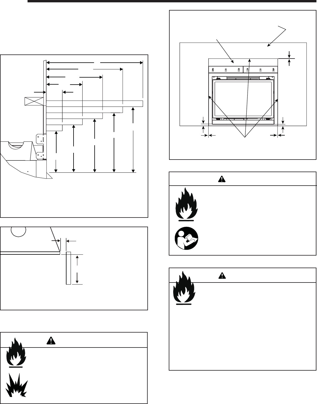
Figure 11.1 shows the minimum vertical and correspond-
ing maximum horizontal dimensions of appliance mantels
or other combustible projections above the top front edge
of the appliance.
11
11
Finishing
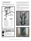
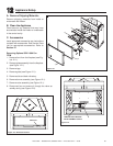
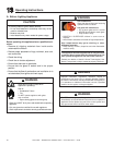
B. Facing Material
Figure 11.3 Noncombustible Facing
Fire Risk.
Finish all edges and fronts to clearances and
specifi cations listed in manual.
• Do NOT overlap combustible materials onto appliance
front. The appliance front may only be covered with
noncombustible materials. The bottom one inch of the
appliance front is exempt and may be covered with either
non-combustible or combustible materials.
• Install combustible materials only up to specified
clearances on top, front and side.
• Seal joints between the fi nished wall and appliance top
and sides using only a 300º F minimum sealant.
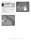
Figure 11.2 Mantel leg or Wall projections
(Acceptable on both sides of opening.)
Figure 11.1 Clearances to mantels or other combustibles
above appliance
Risk of Fire
• Non-combustible clearances MUST be
maintained.
• Sheetrock, wood or other combustibles must
NOT be used as sheathing or facing in the
non-combustible zone.
• See Section 11 for proper clearances.
• See Section 1 for combustible/non-combus-
tible defi nitions.
WARNING
WARNING
SEALANT MATERIAL
0 in.
FINISH WALL MATERIAL MAY BE
COMBUSTIBLE - TOP AND SIDES
0 in.
0 in.
NON-COMBUSTIBLE
BOARD
1 in.
1 in.
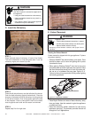
Fire Risk
Explosion Risk
• Facing and/or fi nishing materials must never
overhang into the glass opening.
• Overhanging materials may ignite.
• May interfere with proper operation of glass
assembly.
WARNING
18
14-1/4
10-1/2
6-3/4
3
7-1/4
8-3/8
9-1/2
10-1/8
11-1/4
NOTE: Measurement is taken from top of the opening,
NOT the top of the fi replace.
Note: All
measurements
in inches.
TOP VIEW
1 in. MIN.
3 ft. MAX.
MANTEL
LEG