


Heat & Glo • 6000GCF-IPI, 6000GCF-IPILP • 2110-900 Rev. F • 6/0818
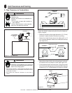
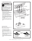
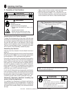
B. Wall Penetration Framing
Combustible Wall Penetration
Frame a hole in a combustible wall for an interior wall
shield fi restop, (Figure 6.3) whenever a wall is penetrated.
Use same size framing materials as those used in the wall
construction. The wall shield fi restop maintains minimum
clearances and prevents cold air infi ltration.
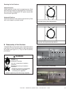
Non-Combustible Wall Penetration
If the hole being penetrated is surrounded by noncombus-
tible materials such as concrete, a hole with diameter one
inch greater than the pipe is acceptable.
Whenever a non-combustible wall is penetrated, the wall
shield fi restop is only required on one side and no heat
shield is necessary.
If your local inspector requires the wall shield fi restop on
both sides, then both wall shield fi restops must have a heat
shield attached to them.
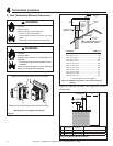
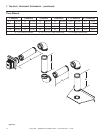
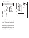
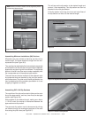
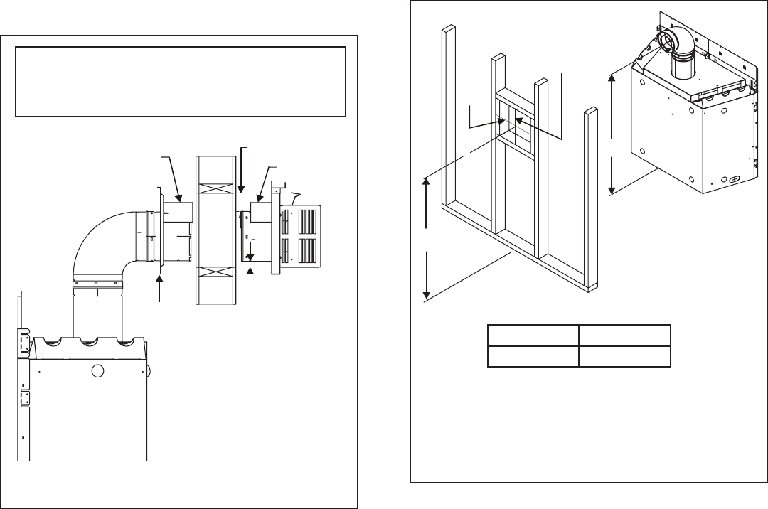
Figure 6.5 Horizontal venting clearances to combustible
materials
NOTE: Heat shields MUST overlap by a minimum of 1-1/2 in. (38 mm).
The heat shield is designed to be used on a wall 4 in. to 7-1/4 in.
(102 mm to 184 mm) thick. If wall thickness is less than 4 in. (102
mm) the existing heat shields must be fi eld trimmed. If wall thickness is
greater than 7-1/4 in. (184 mm) a DVP-HSM-B will be required.
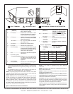
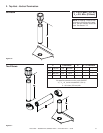
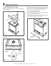
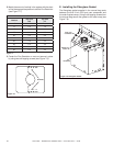
Figure 6.6 Exterior Wall Hole
* Shows center of 10” x 12” vent framing hole for top
venting. The center of the hole is (1) inch (25.4 mm)
above the center of the horizontal vent pipe. With
minimum vertical or 12 inch and 90º elbow.
HEAT
SHIELD
3 IN. TOP
CLEARANCE
HEAT
SHIELD
WALL
WALL
SHIELD
FIRESTOP
1 IN. CLEARANCE
BOTTOM SIDES
A* B
49-1/2 in. 48-1/2 in.
A
B
12 in.
10 in.