


Heat & Glo • 6000GCF-IPI, 6000GCF-IPILP • 2110-900 Rev. F • 6/08 13
V
1
H1
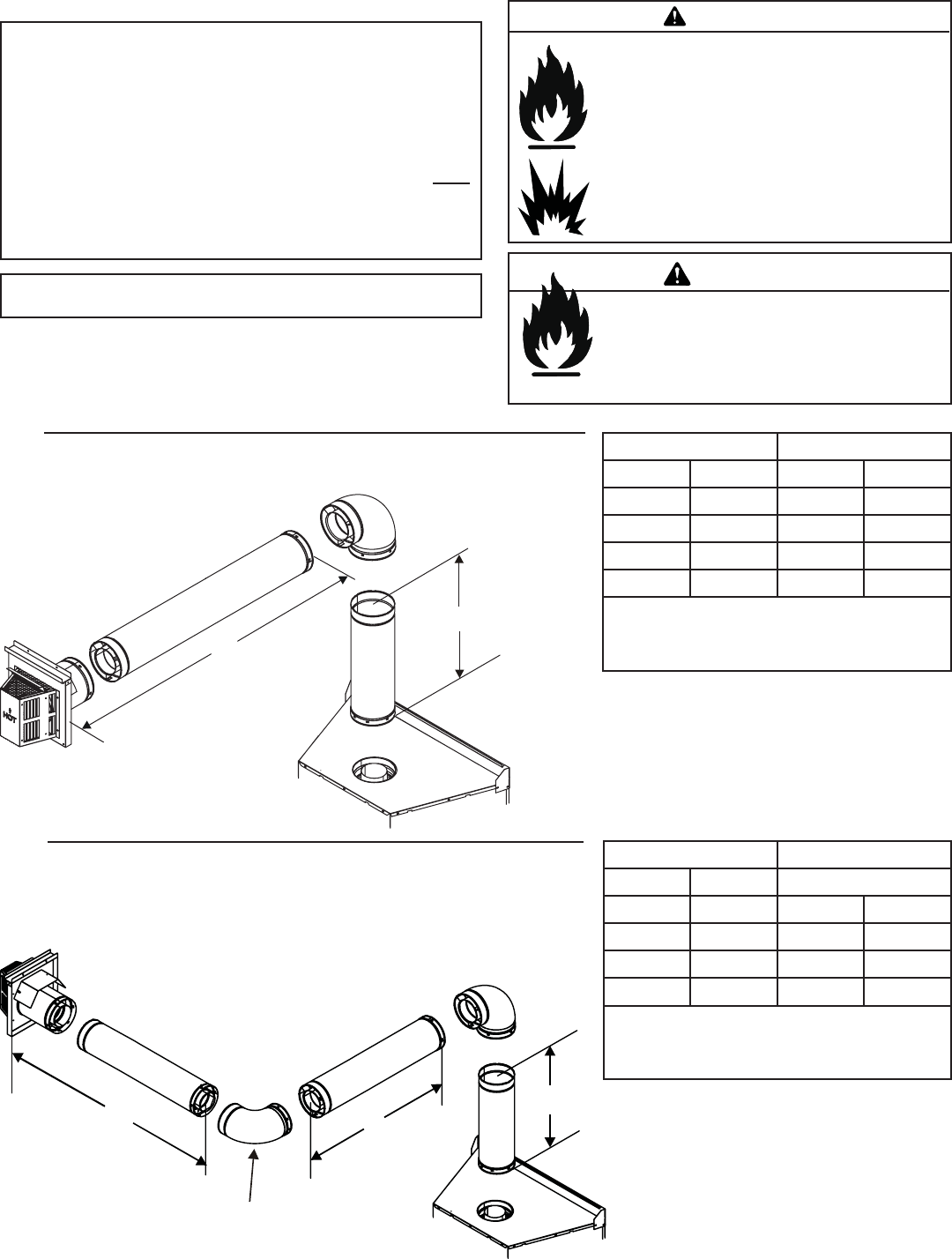
Figure 5.3
Figure 5.4
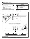
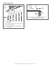
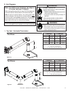
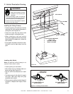
D. Vent Diagrams
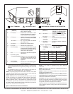
1. Top Vent - Horizontal Termination
One Elbow
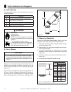
Two Elbows
H
2
H
1
V
1
INSTALLED
HORIZONTALLY
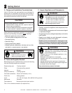
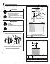
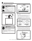
Fire Risk. Explosion Risk.
Do NOT pack insulation or other combustibles
between ceiling fi restops.
• ALWAYS maintain specifi ed clearances around
venting and fi restop systems.
• Install wall shield and ceiling firestops as
specifi ed.
Failure to keep insulation or other material
away from vent pipe may cause fi re.
WARNING
V
1
Minimum H
1
Maximum
6 inches 152 mm 3 ft 914 mm
1 ft 305 mm 3 ft 914 mm
2 ft 610 mm 6 ft 1.8 m
3 ft 914 mm 9 ft 2.7 m
4 ft 1.2 m 12 ft 3.7 m
V
1
+ H
1
= 40 ft (12.2 m) Maximum
H
1
= 20 ft (6.1 m) Maximum
V
1
= 6 inches (152 mm) Minimum
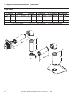
V
1
Minimum H
1
+ H
2
Maximum
1 ft 305 mm Cannot do
1-1/2 ft 457 mm 1-1/2 ft 457 mm
2 ft 610 mm 3 ft 914 mm
3 ft 914 mm 6 ft 1.8 m
4 ft 1.2 m 9 ft 2.7 m
V
1
+ H
1
+ H
2
= 50 ft (15.2 m) Maximum
H
1
+ H
2
= 17 ft (5.2 m) Maximum
V
1
= 1-1/2 ft (457 mm) Minimum
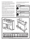
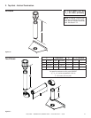
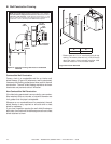
Note: The 6000 series fi replaces can adapt to
SL series vent pipe, if desired.
When venting off the top of the unit, use a DVP-2SL adapter and
a minimum 48 inch vertical section of SL series vent pipe.
After the 48 inch vertical section, the venting table rules
must be followed. The fi rst 48 inch vertical section is NOT
counted as part of the vertical components in the table. It is
still counted as part of the overall maximum run. All venting
table rules for the vent run must still be followed.
Example:
DVP pipe 3 ft. min. vertical = 11 ft. max. horizontal
SL pipe 7 ft. min. vertical = 11 ft. max. horizontal
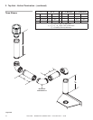
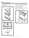
Fire Risk.
• When using DVP-HRC-SS and DVP-HRC-ZC-
SS termination caps on top vented fi replaces, a
6 inch minimum vertical vent section is required
before installing fi rst elbow.
WARNING