


Heat & Glo • 6000GCF-IPI, 6000GCF-IPILP • 2110-900 Rev. F • 6/0812
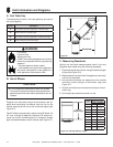
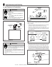
Fire Hazard.
Explosion Risk.
Asphyxiation Risk.
Do NOT connect this gas appliance to a chimney
fl ue serving a separate solid-fuel or gas burning
appliance.
• Vent this appliance directly outside.
• Use separate vent system for this appliance.
May impair safe operation of this appliance or
other appliances connected to the fl ue.
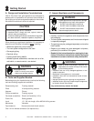
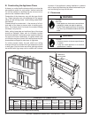
CAUTION
ALL vent confi guration specifi cations MUST be followed.
• This product is tested and listed to these specifi cations.
• Appliance performance will suffer if specifi cations are not
followed.
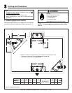
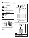
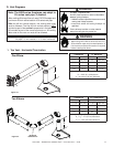
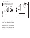
B. Use of Elbows
Diagonal runs have both vertical and horizontal vent as-
pects when calculating the effects. Use the rise for the
vertical aspect and the run for the horizontal aspect (see
Figure 5.1).
Two 45º elbows may be used in place of one 90º elbow. On
45º runs, one foot of diagonal is equal to 8.5 inches hori-
zontal run and 8.5 inches vertical run. A length of straight
pipe is allowed between two 45º elbows (see Figure 5.1).
Figure 5.1
5
5
Vent Information and Diagrams
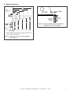
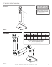
A. Vent Table Key
The abbreviations listed in this vent table key are used in
the vent diagrams.
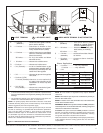
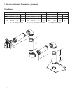
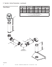
C. Measuring Standards
Vertical and horizontal measurements listed in the vent
diagrams were made using the following standards.
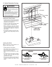
1. Pipe measurements are shown using the effective length
of pipe (see Figure 5.2).
2. Measurements are made from the appliance outer wrap,
not from the standoffs.
3. Horizontal terminations are measured to the outside
mounting surface (fl ange of termination cap) (see
Figure 4.1).
4. Vertical terminations are measured to bottom of termi-
nation cap.
5. Horizontal pipe installed level with no rise.
Figure 5.2 DVP Pipe Effective Length
Effective
Height/Length
Symbol Description
V
1
First section (closest to appliance) of vertical length
V
2
Second section of vertical length
H
1
First section (closest to appliance) of horizontal length
H
2
Second section of horizontal length
Horizontal
Vertical
8-1/2 in.
8-1/2 in.
12 in.
Pipe
Effective Length
Inches Millimeters
DVP4 4 102
DVP6 6 152
DVP12 12 305
DVP24 24 610
DVP36 36 914
DVP48 48 1219
DVP6A 3 to 6 76 to 152
DVP12A 3 to 12 76 to 305
DVP12MI 3 to 12 76 to 305
DVP24MI 3 to 24 76 to 610
WARNING