


Heat & Glo • 6000GCF-IPI, 6000GCF-IPILP • 2110-900 Rev. F • 6/0826
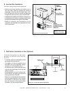
C. Installing Heat Shield and Horizontal Termination Cap
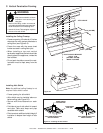
Installing the Horizontal Termination Cap
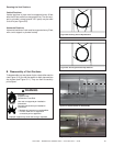
Vent termination must not be recessed in the wall. Siding
may be brought to the edge of the cap base.
Flash and seal as appropriate for siding material at outside
edges of cap.
When installing a horizontal termination cap, follow the cap
location guidelines as prescribed by current ANSI Z223.1
and CAN/CGA-B149 installation codes.
Burn Risk
• Local codes may require installation of a cap
shield to prevent anything or anyone from
touching the hot cap.
Fire Hazard
Impaired performance of appliance
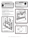
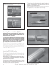
• Telescoping flue section of termination cap
MUST be used when connecting pipe section
to termination cap.
• Maintain a 1-1/2 inch minimum overlap on
telescoping fl ue section of termination cap.
Fire Risk
Exhaust Fumes Risk
Impaired Performance of Appliance
• Overlap pipe slip sections at least 1-1/2 inches.
• Use pilot holes for screws.
• Screws must not exceed 1 inch long.
• Pipe may separate if not properly joined.
WARNING
WARNING
WARNING
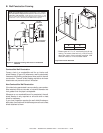
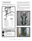
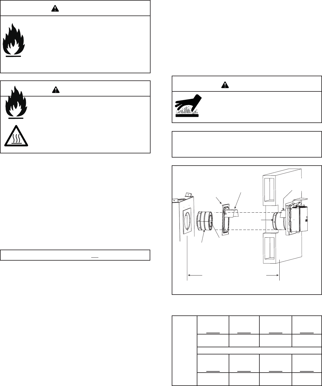
Heat Shield Requirements for Horizontal Termination
For all horizontally vented appliances, a heat shield MUST
be placed one inch above the top of the vent between the
wall shield fi restop and the base of the termination cap.
There are two sections of the heat shield. One section
is factory-attached to the wall shield fi restop. The other
section is factory-attached to the cap. See Figure 8.12.
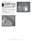
If the wall thickness does not allow the required 1-1/2 inch
(38 mm) heat shield overlap when installed, an extended
heat shield (DVP-HSM-B) must be used.
Important Notice: Heat shields may not be fi eld constructed.
The extended heat shield (DVP-HSM-B) may need to
be cut to length. You will attach the cut heat shield to
the existing cap heat shield or wall shield fi restop heat
shield (refer to Figure 8.12) using the supplied screws.
You MUST maintain a 1-1/2 in. (38 mm) overlap of the
extended heat shield and the existing shields (both ends
of the heat shield). The small leg on the extended heat
shield should rest on the top of the vent (pipe section) to
properly space it from the pipe section.
Note: Where required, an exterior wall fl ashing is available.
When penetrating a brick wall, a brick extension kit is available
for framing the brick.
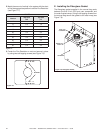
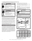
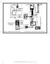
Figure 8.12 Venting through the Wall
INTERIOR
HEAT SHIELD OR
EXTENDED
HEAT SHIELD
WALL SHIELD
FIRESTOP
HEAT SHIELD
1-1/2 IN. (38 MM) MIN.
OVERLAP
SHEATHING
VENT DEPTH FROM BACK OF APPLIANCE TO
OUTSIDE SURFACE OF EXTERIOR WALL
(SEE CHART BELOW)
SLIP SECTION
CAN BE EXTENDED
INNER VENT
OUTER VENT
EXTERIOR
Termination Cap Specifi cation Chart
(depth without using additional pipe sections)
6000GCF
DVP-TRAPK1
Top Vent
Depth
DVP-TRAP1
Rear Vent
Depth
DVP-TRAPK2
Top Vent
Depth
DVP-TRAP2
Rear Vent
Depth
4-1/8 in. to
6 in.
NA
6-5/8 in. to
10-5/8 in.
NA
DVP-HPC1
Top Vent
Depth
DVP-HPC1
Rear Vent
Depth
DVP-HPC2
Top Vent
Depth
DVP-HPC2
Rear Vent
Depth
4-1/8 in. to
6-1/4 in.
NA
6-1/8 in. to
10-1/4 in.
NA
DVP-TRAP1 can adjust 1-7/8 in. (4-3/16 to 6-1/16)
DVP-TRAP2 can adjust 4 in. (6-9/16 to 10-9/16)
DVP-HPC1 can adjust 2-1/8 in. (4-1/4 to 6-3/8)
DVP-HPC2 can adjust 4-1/8 in. (6-3/8 to 10-1/2)