


Heat & Glo • 6000GCF-IPI, 6000GCF-IPILP • 2110-900 Rev. F • 6/08 33
WHT
WHT
BLK
BLK
GRN wire
inside box
Copper
ground attached
to GRN screw with
GRN wire
14/2WG
Cover Plate
outside firebo
x
Romex
Connector
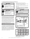
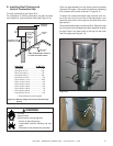
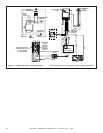
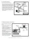
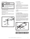
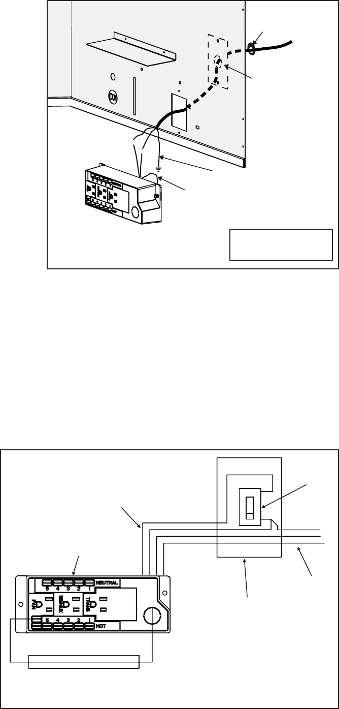
E. Junction Box Installation
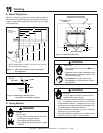
F. Wall Switch Installation for Fan (Optional)
Figure 10.2 Junction Box Detail
Figure 10.4 Junction Box Wired to Wall Switch
If the box is being wired to a wall mount-
ed switch for use with a fan (See Fig-
ure 10.4):
• The power supply for the appliance must
be brought into a switch box.
• The power can then be supplied from
the switch box to the appliance using a
minimum of 14-3 with ground wire.
• At the switch box connect the black (hot)
wire and red (switch leg) wire to the wall
switch as shown.
• At the appliance connect the black (hot),
white (neutral) and green (ground) wires
to the junction box as shown.
• Add a 1/4 inch insulated female connector
to the red (switch leg) wire, route it through
the knockout in the face of the junction
box, and connect to the top fan switch
connector (1/4 inch male) as shown.
NOTE: Do NOT wire
110VAC to wall switch.
Red
Red
Black
Black
Green
Green
White
White
Red
Black
Green
White
SWITCH BOX
JUNCTION BOX
POWER
SUPPLY WIRES
SWITCH
MINIMUM 14-3 AWG
WITH GROUND
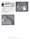
If the box is being wired from the appliance:
• Remove the screw attaching the junction box to
the outer shell, rotate the junction box inward to
disengage it from the outer shell (see Figure 10.2).
• Pull the electrical wires from outside the appliance
through this opening into the valve compartment.
• Loosen the two screws on the Romex connector (not
included with unit), feed the necessary length of wire
through the connector and tighten the screws.
• Make all necessary wire connections to the
receptacle and assemble the receptacle and cover
to the junction box.