


Heat & Glo • 6000GCF-IPI, 6000GCF-IPILP • 2110-900 Rev. F • 6/08 31
A. Recommendation for Wire
This appliance requires 110-120 VAC be wired to the junc-
tion box either for proper operation of the appliance.
10
10
Electrical Information
NOTE: This appliance must be electrically wired and grounded
in accordance with local codes or, in the absence of local
codes, with National Electric Code ANSI/NFPA 70-latest
edition or the Canadian Electric Code, CSA C221.1.
B. Connecting to the Appliance
Wire 110V to electrical junction box.
Do NOT wire 110V to valve.
Do NOT wire 110V to wall switch.
• Incorrect wiring will damage millivolt valves.
• Incorrect wiring will override IPI safety lockout
and may cause explosion.
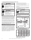
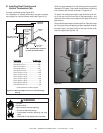
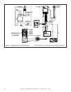
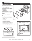
C. Intellifi re Ignition System Wiring
This appliance requires a 110 VAC supply to the appliance
junction box for operation. A wiring diagram is shown in
Figure 10.1.
This appliance is equipped with an Intellifi re control valve
which operates on a 3 volt system.
This appliance is supplied with a battery pack and a 3 volt
AC transformer, which requires the installation of the sup-
plied junction box. It is highly recommended that the junc-
tion box be installed at this time to avoid reconstruction.
The battery pack requires two D cell batteries (not included).
CAUTION
Battery polarity must be correct or module damage will
occur.
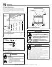
Optional Accessories Requirements
Wiring for optional accessories should be done now to
avoid reconstruction.
• This appliance may be used with a wall switch, wall
mounted thermostat and/or a remote control.
• If using thermostat use one compatible with a millivolt
gas valve system.
• Follow parameters for locating thermostat (see individual
thermostat instructions) to ensure proper operation of
appliance.
• Use low resistance thermostat wire for wiring from ignition
system to the wall switch and thermostat.
• Keep wire lengths short as possible by removing any
excess wire length.
• Low voltage and 110 VAC voltage cannot be shared
within the same wall box.
WARNING
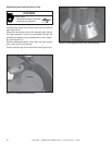
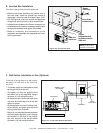
D. Wall Switch
Position the wall switch in the desired position on the
wall. An assembly of 18 ft of 20 AWG is provided with
the fi replace to connect the wall switch to the appliance.
Instead of the supplied assembly, wire with a length of
25 ft or less and a gauge of 20 AWG through 14 AWG is
acceptable. The wire needs a jacket with a temperature
rating of 140º F (60º C) or higher. At the appliance con-
nect the wire to the ON/OFF switch pigtails.
Note: Batteries cannot be placed in the battery pack while
using the 3 volt AC transformer. The transformer must be
unplugged if the battery pack is used or battery life will
be reduced.
CAUTION
Label all wires prior to disconnection when servicing controls.
Wiring errors can cause improper and dangerous operation.
Verify proper operation after servicing.
Shock hazard.
• Replace damaged wire with type 105º C rated
wire.
• Wire must have high temperature insulation.
WARNING