


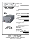


Submittal Data HBH SerieS Heat Controller, Inc.
Engineering Design Guide HBH SERIES Heat Controller, Inc.
3
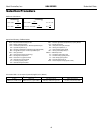
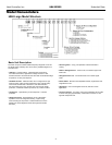
Step 1 Determine the actual heating and cooling loads at the
desired dry bulb and wet bulb conditions.
Step 2 Obtain the following design parameters: Entering water
temperature, water ow rate in GPM, air ow in CFM,
water ow pressure drop and design wet and dry bulb
temperatures. Air ow CFM should be between 300 and
450 CFM per ton. Unit water pressure drop should be kept
as close as possible to each other to make water balancing
easier. Go to the appropriate tables and nd the proper
indicated water ow and water temperature.
Step 3 Select a unit based on total and sensible cooling
conditions. Select a unit which is closest to the actual
cooling load.
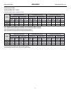
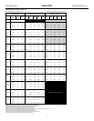
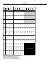
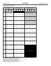
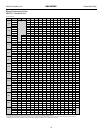
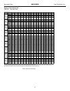
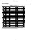
Step 4 Use data from performance tables at the design water ow
and water temperature. Read the total and sensible cooling
capacities (Note: interpolation is permissible, extrapolation
is not).
Step 5 Read the heating capacity. If it exceeds the design criteria
it is acceptable. It is quite normal for Water-Source Heat
Pumps to be selected on cooling capacity only since the
heating output is usually greater than the cooling capacity.
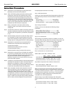
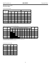
Step 6 Determine the correction factors associated with the
variable factors of dry bulb and wet bulb (page 14).
Corrected Total Cooling =
tabulated total cooling x wet bulb correction.
Corrected Sensible Cooling =
tabulated sensible cooling x wet/dry bulb correction.
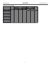
Step 7 Determine the correction factor associated with antifreeze
in system loop. If heating EWT is 50°F or below you may
have to use antifreeze. Calculate leaving water temperature
per performance data selection notes (page 18). If
antifreeze is required, use correction table for correcting
total and sensible capacities.
Step 8 Compare the corrected capacities to the load requirements.
Normally if the capacities are within 10% of the loads, the
equipment is acceptable. It is better to undersize than
oversize, as undersizing improves humidity control, reduces
sound levels and extends the life of the equipment.
Step 9 When completed, calculate water temperature rise and
assess the selection. If the units selected are not within
10% of the load calculations, then review what eect
changing the GPM, water temperature and/or air ow and
air temperature would have on the corrected capacities. If
the desired capacity cannot be achieved, select the next
larger or smaller unit and repeat the procedure. Remember,
when in doubt, undersize slightly for best performance.
Example Equipment Selection For Cooling
Step 1 Load Determination:
Assume you have determined that the appropriate cooling load
at the desired dry bulb 80°F and wet bulb 65°F conditions is as
follows:
Total Cooling.................................................90,500 BTUH
Sensible Cooling...........................................73,300 BTUH
Entering Air Temp...........80°F Dry Bulb / 65°F Wet Bulb
Step 2 Design Conditions:
Similarly, you have also obtained the following design
parameters:
Entering Water Temp (Cooling).................................90°F
Entering Water Temp (Heating).................................60°F
Water Flow (Based upon 12°F rise in temp.)......18 GPM
Air Flow..............................................................2,800 CFM
Step 3, 4 & 5 HP Selection:
After making your preliminary selection (TCH096), we enter the
data from tables at design water ow and water temperature and
read Total Cooling, Sens. Cooling and Heat of Rej. capacities:
Total Cooling....................................................93,200 BTUH
Sensible Cooling..............................................70,390 BTUH
Heat of Rejection...........................................120,100 BTUH
Airow...................................................................3,200 CFM
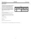
Step 6, 7 & 8 Entering Air, Airow and Antifreeze Corrections:
Next, we determine our correction factors.
Airow 2800 ÷ 3200 = 88% Antifreeze - None
Table Ent Air Air Flow Corrected
Corrected Total Cooling = 93,200 x .977 x .976 x 1 = 88,871
Corrected Sens Cooling = 70,390 x 1.088 x .933 x 1=71,453
Corrected Heat of Rej. = 120,100 x .998 x .976 =116,983
Step 9 Water Temperature Rise Calculation & Assessment:
Rise = Heat of Reject ÷ (GPM x 500)
Actual Temperature Rise 116,983 ÷ 9,000 = 13.0°F
When we compare the Corrected Total Cooling and Corrected
Sensible Cooling gures with our load requirements stated in Step
1, we discover that our selection is within +/- 10% of our sensible
load requirement. Furthermore, we see that our Corrected Total
Cooling gure is slightly undersized as recommended, when
compared to the actual indicated load.
Alternate Step 7: If your EWT for heating is 40°F then system
requires antifreeze. If a solution of 15% Propylene Glycol is required,
then:
Corrected Total Cooling = 88,871 x .986 = 87,626
Corrected Sens Cooling = 71,453 x .986 = 70,452
Selection Procedure