


Heat Controller, Inc. HBH SerieS Submittal Data
Heat Controller, Inc. HBH SERIES Engineering Design Guide
24
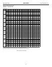
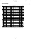
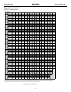
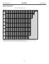
HBH Series 60Hz
Engineering Specications Page 3
Fan and Motor Assembly:
All units shall have belt-driven single centrifugal fan. Fan motor shall be permanently lubricated with thermal overload protection. Units
supplied without permanently lubricated motors must provide external oilers for easy service. The fan and motor assembly must be
capable of overcoming the external static pressures as shown on the schedule. Airow/Static pressure rating of the unit shall be based
on a wet coil and a clean lter in place. Ratings based on a dry coil and/or no lter, or on an ESP less than 0.25” (6.35 mm w.g.)
shall NOT be acceptable.
Option: Various blower drive packages for selectable static pressure/airow.
Refrigerant Circuit:
All units shall contain R-410A sealed refrigerant circuit including a high efciency scroll compressor designed for heat pump operation,
a thermostatic expansion valve for refrigerant metering, an enhanced corrugated aluminum lanced n and ried copper tube refrigerant
to air heat exchanger, reversing valve, coaxial (tube in tube) refrigerant to water heat exchanger, and safety controls including a high
pressure switch, low pressure switch (loss of charge), water coil low temperature sensor, and air coil low temperature sensor. Access
ttings shall be factory installed on high and low pressure refrigerant lines to facilitate eld service. Activation of any safety device
shall prevent compressor operation via a microprocessor lockout circuit. The lockout circuit shall be reset at the thermostat or at the
contractor supplied disconnect switch. Units that cannot be reset at the thermostat shall not be acceptable.
Hermetic compressors shall be internally sprung. The scroll compressors shall have a dual level vibration isolation system. The
compressor(s) will be mounted on specially engineered sound-tested EPDM vibration isolation grommets to a large heavy gauge
compressor mounting plate, which is then isolated from the cabinet base with rubber grommets for maximized vibration attenuation.
Compressor shall have thermal overload protection. Compressor shall be located in an insulated compartment isolated from air stream
to minimize sound transmission.
Refrigerant to air heat exchangers shall utilize enhanced corrugated lanced aluminum ns and ried copper tube construction rated to
withstand 625 PSIG (4309 kPa) refrigerant working pressure. Refrigerant to water heat exchangers shall be of copper inner water tube
and steel refrigerant outer tube design, rated to withstand 625 PSIG (4309 kPa) working refrigerant pressure and 500 PSIG (3445 kPa)
working water pressure. The refrigerant to water heat exchanger shall be “electro-coated” with a low cure cathodic epoxy material a
minimum of 0.4 mils thick (0.4 – 1.5 mils range) on all surfaces. The black colored coating shall provide a minimum of 1000 hours salt
spray protection per ASTM B117-97 on all external steel and copper tubing. The material shall be formulated without the inclusion of
any heavy metals and shall exhibit a pencil hardness of 2H (ASTM D3363-92A), crosshatch adhesion of 4B-5B (ASTM D3359-95), and
impact resistance of 160 in-lbs (184 kg-cm) direct (ASTM D2794-93).
Refrigerant metering shall be accomplished by thermostatic expansion valve only. Expansion valves shall be dual port balanced type
with external equalizer for optimum refrigerant metering. Units shall be designed and tested for operating ranges of entering water
temperatures from 20° to 120°F (-6.7° to 48.9°C). Reversing valve shall be four-way solenoid activated refrigerant valve, which shall
default to heating mode should the solenoid fail to function. If the reversing valve solenoid defaults to cooling mode, an additional low
temperature thermostat must be provided to prevent over-cooling an already cold room.
Option: The unit shall be supplied with cupro-nickel coaxial water to refrigerant heat exchanger.
Option: The unit shall be supplied with extended range Insulation option, which adds closed cell insulation to internal water lines, and
provides insulation on suction side refrigeration tubing including refrigerant to water heat exchanger.
Option: The refrigerant to air heat exchanger shall be “electro-coated” with a low cure cathodic epoxy material a minimum of 0.4
mils thick (0.4 – 1.5 mils range) on all surfaces. The black colored coating shall provide a minimum of 1000 hours salt spray
protection per ASTM B117-97 on all galvanized end plates and copper tubing, and a minimum of 2000 hours of salt spray on all
aluminum ns. The material shall be formulated without the inclusion of any heavy metals and shall exhibit a pencil hardness
of 2H (ASTM D3363-92A), crosshatch adhesion of 4B-5B (ASTM D3359-95), and impact resistance of 160 in-lbs (184 kg-cm)
direct (ASTM D2794-93).
Drain Pan:
The drain pan shall be constructed of galvanized steel and have a powder coat paint application to further inhibit corrosion. This
corrosion protection system shall meet the stringent 1000 hour salt spray test per ASTM B117. If plastic type material is used, it must
be HDPE (High Density Polyethylene) to avoid thermal cycling shock stress failure over the lifetime of the unit. Drain pan shall be fully
insulated. Drain outlet shall be located at pan as to allow complete and unobstructed drainage of condensate. Drain pan hose assembly
can be connected to either side, drain outlet to be 1”FPT tting. Choice of drain connection to only one side will not be accepted. The
unit as standard will be supplied with solid-state electronic condensate overow protection. Mechanical oat switches will NOT be
accepted.