


Submittal Data HBH SerieS Heat Controller, Inc.
Engineering Design Guide HBH SERIES Heat Controller, Inc.
25
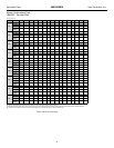
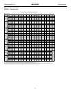
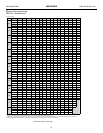
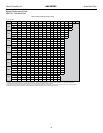
HBH Series 60Hz
Engineering Specications Page 4
Option: The unit shall be supplied with stainless steel drain pan.
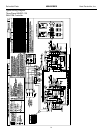
Electrical:
A control box shall be located within the unit compressor compartment and shall contain a 75VA transformer with load side circuit
breaker protection, 24 volt activated, 2 or 3 pole compressor contactor, terminal block for thermostat wiring and solid-state controller for
complete unit operation. Reversing valve and fan motor wiring shall be routed through this electronic controller. Units shall be name-
plated for use with time delay fuses or HACR circuit breakers. Unit controls shall be 24 Volt and provide heating or cooling as required
by the remote thermostat/sensor. Two compressor units shall have a solid-state time delay relay and random start to prevent both
compressors from starting simultaneously.
Solid State Control System (CXM):
Units shall have a solid-state control system. Units utilizing electro-mechanical control shall not be acceptable. The control system
microprocessor board shall be specically designed to protect against building electrical system noise contamination, EMI, and RFI
interference. The control system shall interface with a heat pump type thermostat. The control system shall have the following features:
a. Anti-short cycle time delay on compressor operation.
b. Random start on power up mode.
c. Low voltage protection.
d. High voltage protection.
e. Unit shutdown on high or low refrigerant pressures.
f. Unit shutdown on low water temperature.
g. Condensate overow electronic protection.
h. Option to reset unit at thermostat or disconnect.
i. Automatic intelligent reset. Unit shall automatically reset the unit 5 minutes after trip if the fault has cleared. If a fault occurs 3
times sequentially without thermostat meeting temperature, then lockout requiring manual reset will occur.
j. Ability to defeat time delays for servicing.
k. Light emitting diode (LED) on circuit board to indicate high pressure, low pressure, low voltage, high voltage, low water/air
temperature cut-out, condensate overow, and control voltage status.
l. The low-pressure switch shall not be monitored for the rst 120 seconds after a compressor start command to prevent
nuisance safety trips.
m. 24V output to cycle a motorized water valve or other device with compressor contactor.
n. Unit Performance Sentinel (UPS). The UPS warns when the heat pump is running inefciently.
o. Water coil low temperature sensing (selectable for water or anti-freeze).
p. Air coil low temperature sensing.
NOTE: Units not providing the 8 safety protections of anti-short cycle, low voltage, high voltage, high refrigerant pressure,
low pressure (loss of charge), air coil low temperature cut-out, water coil low temperature cut-out, and condensate overow
protections will not be accepted.
Remote Service Sentinel (CXM):
Solid state control system shall communicate with thermostat to display (at the thermostat) the unit status, fault status, and specic
fault condition, as well as retrieve previously stored fault that caused unit shutdown. The Remote Service Sentinel allows building
maintenance personnel or service personnel to diagnose unit from the wall thermostat. The control board shall provide a signal to
the thermostat fault light, indicating a lockout. Upon cycling the G (fan) input 3 times within a 60 second time period, the fault light
shall display the specic code as indicated by a sequence of ashes. A detailed ashing code shall be provided at the thermostat
LED to display unit status and specic fault status such as over/under voltage fault, high pressure fault, low pressure fault, low water
temperature fault, condensate overow fault, etc. Units that do not provide this remote service sentinel shall not be acceptable.
FIELD INSTALLED OPTIONS
Hose Kits:
All units 120000 BTUH (35 kW) and below shall be connected with hoses. The hoses shall be 2 feet (61cm) long, braided stainless
steel; re rated hoses complete with adapters. Only re rated hoses will be accepted.
Valves:
The following valves are available and will be shipped loose:
a. Ball valve; bronze material, standard port full ow design, FPT connections.
b. Ball valve with memory stop and PT port.
c. “Y” strainer with blowdown valve; bronze material, FPT connections.
d. Motorized water valve; slow acting, 24v, FPT connections.