


Heat Controller, Inc. HBH SerieS Submittal Data
Heat Controller, Inc. HBH SERIES Engineering Design Guide
18
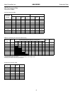
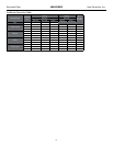
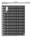
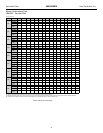
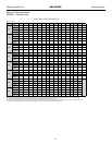
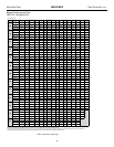
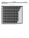
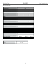
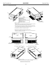
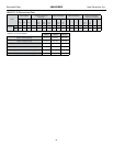
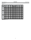
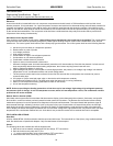
HBH072-120 Dimensional Data
DIMENSIONAL DATA TABLE ON NEXT PAGE
LEFT RETURN STRAIGHT DISCHARGE
CAP
CAP
FRONT
BSP
A
EAP
CBP
B
A
O
P
Q
R
K
M
F
G
E
D
BSP
RIGHT RETURN STRAIGHT DISCHARGE
1
EAP
2 CAP
CAP
2
FRONT
CBP
1
5
4
LEGEND
CAP=Compressor Access Panel
CBP=Control Box Panel
BSP=Blower Service Panel
EAP=Expansion Valve Access panel
1=Water Outlet 1-1/4Ó FPT (072-096) 1-1/2Ó FPT (120)
2=Water Inlet 1-1/4Ó FPT (072-096) 1-1/2Ó FPT (120)
3=Condensate 3/4Ó FPT
4=High Voltage 1-1/8Ó [2.9cm] KO
5=Low Voltage 7/8Ó [2.2cm] KO
HANGER BRACKET DIMENSIONS
87Ó
[221cm]
1.0Ó
[2.54cm]
PLAN VIEW
TOP
4.3Ó
[10.8cm]
34.1Ó
[86.6cm]
FRONT
CONTROL BOX
U
T
S
V
1.3Ó
[3.3cm]
condensate
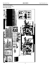
LEFT RETURN LEFT VIEW-
AIR COIL SIDE
LEFT RETURN END DISCHARGE
CBP
EAP
BSP
CAP
CAP
FRONT
E
D
F
G
CAP
CBP
CAP
EAP
BSP
FRONT
FRONT
CONTROL BOX
PLAN VIEW
TOP
V
S
U
RIGHT RETURN RIGHT VIEW-
AIR COIL SIDE
RIGHT RETURN END DISCHARGE
1.3Ó
[3.3cm]
condensate drain
3
NOTES FOR LEGEND:
1. Access is required for all removable panels and installer should take care to comply with
all building codes and allow adequate clearance for future field service.
2. Water inlet and water outlet connections are available on either side (left or right) of the
unit. Qty (2x) MPT Plugs are shipped loose in a plastic bag tied to the water leg in front of
the unit. Installer must plug water inlet/outlet side not being connected to.
3. Condensate drain is available on end opposite compressor.
4. Electrical access is available on either side (left or right) of the front.
5. Electric box is on right side. It can be field converted to left side. Conversion should only
be attempted by qualified service technician.
NOTES:
- All dimensions in inches (cm)
- Units require 3Õ (9.1 cm) clearance for water connections, CAP, CSP, EAP and BSP service access.
- Overall cabinet width dimensions does not include filter rail and duct flange.
SERVICE ACCESS
3Õ (91 cm.) TYPICAL
ALL CONFIGURATIONS
LEFT RETURN STRAIGHT DISCHARGE
CAP
CAP
FRONT
BSP
A
EAP
CBP
B
A
O
P
Q
R
K
M
F
G
E
D
BSP
RIGHT RETURN STRAIGHT DISCHARGE
1
EAP
2 CAP
CAP
2
FRONT
CBP
1
5
4
LEGEND
CAP=Compressor Access Panel
CBP=Control Box Panel
BSP=Blower Service Panel
EAP=Expansion Valve Access panel
1=Water Outlet 1-1/4Ó FPT (072-096) 1-1/2Ó FPT (120)
2=Water Inlet 1-1/4Ó FPT (072-096) 1-1/2Ó FPT (120)
3=Condensate 3/4Ó FPT
4=High Voltage 1-1/8Ó [2.9cm] KO
5=Low Voltage 7/8Ó [2.2cm] KO
HANGER BRACKET DIMENSIONS
87Ó
[221cm]
1.0Ó
[2.54cm]
PLAN VIEW
TOP
4.3Ó
[10.8cm]
34.1Ó
[86.6cm]
FRONT
CONTROL BOX
U
T
S
V
1.3Ó
[3.3cm]
condensate
LEFT RETURN LEFT VIEW-
AIR COIL SIDE
LEFT RETURN END DISCHARGE
CBP
EAP
BSP
CAP
CAP
FRONT
E
D
F
G
CAP
CBP
CAP
EAP
BSP
FRONT
FRONT
CONTROL BOX
PLAN VIEW
TOP
V
S
U
RIGHT RETURN RIGHT VIEW-
AIR COIL SIDE
RIGHT RETURN END DISCHARGE
1.3Ó
[3.3cm]
condensate drain
3
NOTES FOR LEGEND:
1. Access is required for all removable panels and installer should take care to comply with
all building codes and allow adequate clearance for future field service.
2. Water inlet and water outlet connections are available on either side (left or right) of the
unit. Qty (2x) MPT Plugs are shipped loose in a plastic bag tied to the water leg in front of
the unit. Installer must plug water inlet/outlet side not being connected to.
3. Condensate drain is available on end opposite compressor.
4. Electrical access is available on either side (left or right) of the front.
5. Electric box is on right side. It can be field converted to left side. Conversion should only
be attempted by qualified service technician.
NOTES:
- All dimensions in inches (cm)
- Units require 3Õ (9.1 cm) clearance for water connections, CAP, CSP, EAP and BSP service access.
- Overall cabinet width dimensions does not include filter rail and duct flange.
SERVICE ACCESS
3Õ (91 cm.) TYPICAL
ALL CONFIGURATIONS