


Submittal Data HBH SerieS Heat Controller, Inc.
Engineering Design Guide HBH SERIES Heat Controller, Inc.
23
HBH Series 60Hz
Engineering Specications Page 2
General:
Furnish and install the HBH Series as indicated on the plans. Equipment shall be completely assembled, piped and internally wired.
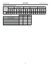
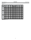
Capacities and characteristics as listed in the schedule and the specications that follow.
Units shall be supplied completely factory built capable of operating over an entering water temperature range from 20° to 120°F
(-6.7° to 48.9°C) as standard. Equivalent units from other manufacturers may be proposed provided approval to bid is given 10 days
prior to bid closing. All equipment listed in this section must be rated and certied in accordance with Air-Conditioning, Heating and
Refrigeration Institute/International Standards Organization (AHRI/ISO 13256-1). All equipment must be tested, investigated, and
determined to comply with the requirements of the standards for Heating and Cooling Equipment UL-1995 for the United States and
CAN/CSA-C22.2 NO.236 for Canada, by Intertek Testing Laboratories (ETL). The units shall have AHRI/ISO and ETL-US-C labels.
All units shall be fully quality tested by factory run testing under normal operating conditions as described herein. Quality control system
shall automatically perform via computer: triple leak check, pressure tests, evacuation and accurately charge system, perform detailed
heating and cooling mode tests, and quality cross check all operational and test conditions to pass/fail criteria. Detailed report card will
ship with each unit displaying status for critical tests and components. Note: If unit fails on any cross check, it shall not be allowed
to ship. Serial numbers will be recorded by factory and furnished to contractor on report card for ease of unit warranty status.
Units tested without water ow are not acceptable.
Basic Construction:
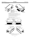
Horizontal units shall have one of the following air ow arrangements: Left Return/Back Discharge, Left Return/Straight Discharge,
Right Return/Back Discharge, Right Return/Straight Discharge as shown on the plans. Units can be eld converted without
requiring new panels or belts. Units that cannot be eld converted shall not be acceptable.
If units with these arrangements are not used, the contractor is responsible for any extra costs incurred by other trades. All units
must have a minimum of two access panels for serviceability of compressor compartment. Units having only one access panel to
compressor/heat exchangers/expansion device/refrigerant piping shall not be acceptable.
Compressor section interior surfaces shall be lined with 1/2 inch (12.7mm) thick, 1-1/2 lb/ft3 (24 kg/m3) acoustic type glass ber
insulation. Air handling section interior surfaces shall be lined with 1/2 in (12.7mm) thick, 1-3/4 lb/ft3 (28 kg/m3) foil backed ber
insulation for ease of cleaning. Insulation placement shall be designed in a manner that will eliminate any exposed edges to prevent the
introduction of glass bers into the air stream. Units without foil faced insulation in the air handling section will not be accepted.
Horizontal heat pumps shall be fabricated from heavy gauge galvanized steel, with powder coat paint nish on front access panel. Color
to be pewter. Both sides of the panel shall be painted for added protection.
Standard insulation must meet NFPA Fire Hazard Classication requirements 25/50 per ASTM E84, UL 723, CAN/ULC S102-M88 and
NFPA 90A requirements; air erosion and mold growth limits of UL-181; stringent fungal resistance test per ASTM-C1071 and ASTM
G21; and shall meet zero level bacteria growth per ASTM G22. Unit insulation must meet these stringent requirements or unit(s)
will not be accepted.
Horizontal units to have discharge air duct collar and 1” (25.4mm) lter rails with 1” (25.4mm) lters factory installed and factory
installed mounting brackets. If units with these factory installed provisions are not used, the contractor is responsible for any
extra costs to eld install these provisions, and/or the extra costs for his sub-contractor to install these provisions.
All units must have an insulated panel separating the fan compartment from the compressor compartment. Units with the compressor in
the air stream are not acceptable. Units shall have a factory installed 1 inch (25.4mm) wide lter rails with lter removal from either side.
Units shall have a 1 inch (25.4mm) thick throwaway type glass ber lter. The contractor shall purchase one spare set of lters and
replace factory shipped lters on completion of start-up. Filters shall be standard sizes. If units utilize non-standard lter sizes then the
contractor shall provide 12 spare lters for each unit.
Cabinets shall have separate knockouts on front and sides for entrance of line voltage and low voltage control wiring. All factory-
installed wiring passing through factory knockouts and openings shall be protected from sheet metal edges at openings by plastic
ferrules. Supply and return water connections shall be copper FPT ttings, connections on both sides (installer to choose side and plug
opposite) and shall be securely mounted ush to the cabinet side allowing for connection of a exible hose without the use of a back-
up wrench. Water connections that protrude through the cabinet or require the use of a backup wrench shall not be allowed.
Water connections on only one side will not be accepted. All water connections and electrical knockouts must not interfere with the
serviceability of unit. Contractor shall be responsible for any extra costs involved in the installation of units that do not have
this feature. Contractor must ensure that units can be easily removed for servicing and coordinate locations of electrical conduit and
lights with the electrical contractor.