


20
ASSEMBLY
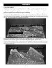
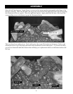
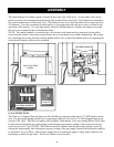
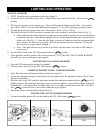
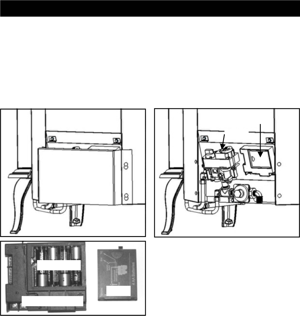
The main heating valve battery pack is located at the center rear of the stove. A removable valve access
panel covers the valve components and simply lifts up and off the stove back. The batteries are located in
the control module next to the actual valve. The battery access cover lifts and slides off to expose the four
AA batteries. Note the orientation of each battery as you replace the old with new as this is critical to the
operation of the control. Use only high quality long-life alkaline batteries. Replace the battery cover and
the valve access panel. Refer to illustrations below.
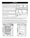
NOTE: The control module is secured to the valve bracket with hook-and-eye strips and can be pulled
away from the bracket if necessary to gain better access to the battery cover and compartment. Be certain
not to dislodge the wiring from the control module and be sure to place the module back it its original posi-
tion after the batteries and cover are installed.
CONTROL MODULE
COVER
AA BATTERIES
VALVE ACCESS
PANEL
CONTROL MODULE
VALVE
GAS CONNECTION
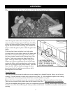
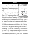
The FireLuxe is shipped from the factory with a flexible gas connector that has a 1/2” NPT female connec-
tion. The gas supply piping should have a separate gas shut-off valve and a 1/8” NPT plugged tapping up-
stream of the valve. The FireLuxe and its inlet regulator. Main burner valve and cooking burner valve must
be disconnected from the gas supply piping system during any pressure testing of that system at test pres-
sures in excess of 1/2 psi (3.5kPa). The FireLuxe must be isolated from the gas supply piping system by
closing the main control valve during any pressure testing of the gas supply system at test pressures equal to
or less than 1/2 psi (3.5kPa). After the gas supply has been connected, apply a soapy water solution to all
the fittings to check for gas leaks. Never use a flame to test for leaks.