


18
ASSEMBLY
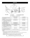
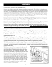
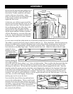
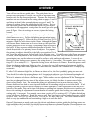
It is now time to install the ashlip on the stove front and to install the stove front and stove top.
The ashlip is secured to the front using two brackets and four 1/4 – 20 hex head bolts. With the front facing
down on a padded surface, align the mounting bosses on the ashlip with the mounting bosses on the front.
Install the two “L”-shaped brackets with the slotted end on the ashlip. Tighten the bolts to the front but
leave the bolts to the ashlip finger tight. Carefully turn the front over. Adjust the ashlip so that it is tight
against the lower
molding on the front.
Tighten the ashlip
bolts. Take care with
an enamel stove to
prevent chipping.
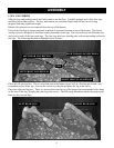
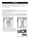
Replace the stove
front by aligning the
outer edges with the
stove sides while the front is about ½ to 1” above its final position. This is to allow the sheet metal tabs that
secure it to the sides to be above the mating cast iron tabs on the sides. Carefully push the front in while
allowing it to slide down. All four tabs (two top and two bottom) should engage with the sides. Once the
front has reached the proper position, check the vertical alignment by looking at the alignment of the edges
of the front to the casting details on the side. They should be parallel. If they are not, simply push or pull
on the front until a good visual alignment is obtained. Take extra care with this procedure if your stove is
enameled. Just move in small increments as you line up the tabs and lower the front into place. If you take
your time, you will avoid chipping. Remove any
masking tape used to secure the doors.
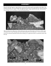
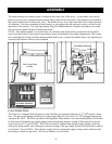
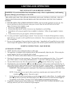
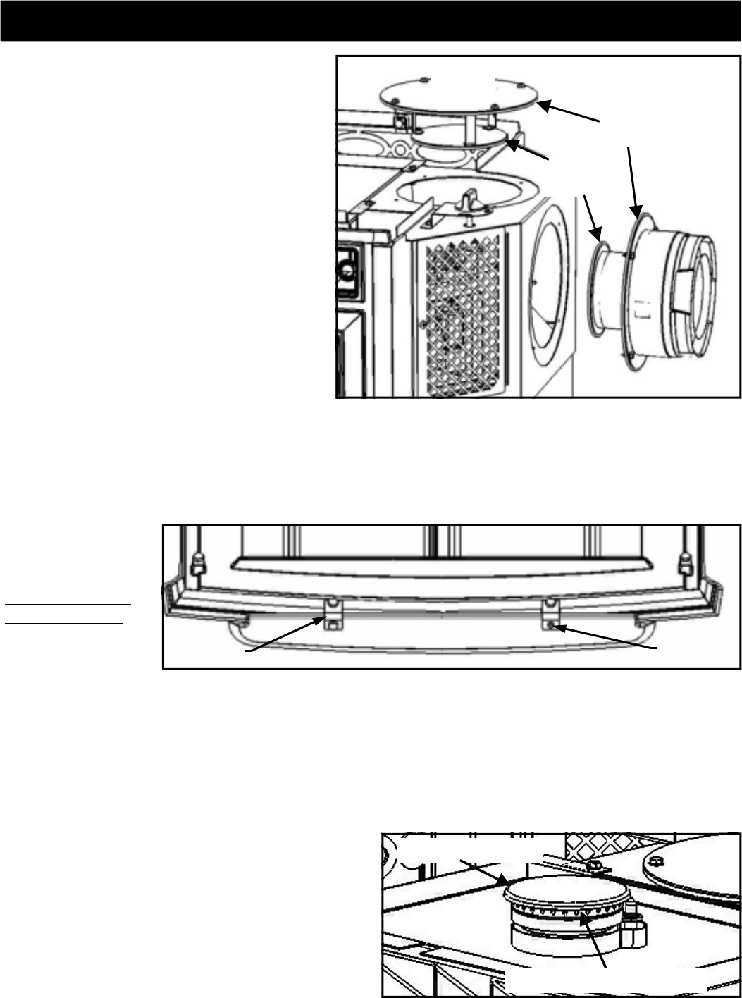
Be sure that the inner and outer gaskets are in
their proper positions. Install and tighten the
four screws. Finally, install the vent starter
section in the rear vent position. Again,
make sure that the inner and outer gaskets are
in their proper positions and install and
tighten the four screws.
INNER
GASKETS
OUTER
GASKETS
STARTER SECTION
COVER
PLATE
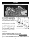
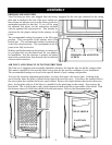
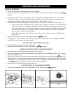
Next, install the brass diffuser ring and top burner
cover on the cooking burner. This is a small round
disk that sits on top of the brass diffuser ring on the
top burner. If you look at the back side of the diffuser,
you will see alignment tabs. They correspond to
alignment locations on the burner. The cover is sim-
ply centered in the diffuser.
BRASS DIFFUSER RING
BURNER COVER
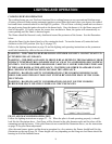
At this time, you will also want to install the
optional cast iron plate that fills in the top vent
cutout on the stove top. With the bottom of
the top facing up, place the filler plate in the
cutout with the filler plate edge molding
aligned with the edge molding on the top. Us-
ing the bracket and three fasteners included
with the filler plate kit, secure the filler plate
to the top. See the illustration included with
the optional filler plate kit for more informa-
tion.
ASHLIP
SLOT
BRACKET
FRONT