


SERVICING
38
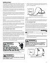
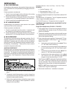
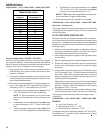
SUBCOOLING = SAT. LIQUID TEMP. - LIQUID LINE TEMP.
Liquid
Pressure
Saturated Liquid
Tem
p
erature °F
PSIG R-410A
200 70
210 73
220 76
225 78
235 80
245 83
255 85
265 88
275 90
285 92
295 95
305 97
325 101
355 108
375 112
405 118
SATURATED LIQUID PRESSURE
TEMPERATURE CHART
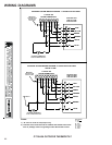
Two Speed Application (*PH1548**-*PH1560**)
Run the unit on low stage cooling for 10 minutes until refriger-
ant pressures stabilize. Follow the guidelines and methods
below to check unit operation and ensure that the refrigerant
charge is within limits. Charge the unit on low stage.
1. Purge gauge lines. Connect service gauge manifold to
access fittings. Run system at least 10 minutes to allow
pressure to stabilize.
2. Temporarily install thermometer on liquid (small) line near
liquid line access fitting with adequate contact and insu-
late for best possible reading.
3. Check subcooling and superheat. Two stage systems run-
ning on low stage with TXV application should have a
subcooling of 5 to 7 ºF and superheat of 15 to 18ºF.
a. If subcooling and superheat are low, adjust TXV to
15 to 18ºF superheat, then check subcooling.
NOTE: To adjust superheat, turn the valve stem
clockwise to increase and counter clockwise to de-
crease.
b. If subcooling is low and superheat is high, add charge
to raise subcooling to 5 to 7 ºF then check super-
heat.
c. If subcooling and superheat are high, adjust TXV
valve to 15 to 18ºF superheat, then check subcooling.
d. If subcooling is high and superheat is low, adjust
TXV valve to 15 to 18ºF superheat and remove
charge to lower the subcooling to 5 to 7 ºF.
NOTE: Do NOT adjust the charge based on suction pres-
sure unless there is a gross undercharge.
4. Disconnect manifold set, installation is complete.
SUBCOOLING = SAT. LIQUID TEMP. - LIQUID LINE TEMP.
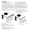
Heat Pump - Heating Cycle
The proper method of charging a heat pump in the heat mode
is by weighing the charge according to the total charge listed
on the rating plate.
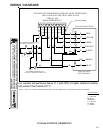
S-109 CHECKING SUBCOOLING
Refrigerant liquid is considered subcooled when its tempera-
ture is lower than the saturation temperature corresponding to
its pressure. The degree of subcooling equals the degrees of
temperature decrease below the saturation temperature at the
existing pressure.
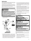
1. Attach an accurate thermometer or preferably a thermo-
couple type temperature tester to the liquid line close to
the high pressure access fitting process tube.
2. Install a high side pressure gauge on the high side (liquid)
access fitting.
3. Record the gauge pressure and the temperature of the line.
4. Review the technical information manual or specification
sheet for the model being serviced to obtain the design
subcooling.
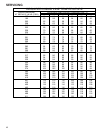
5. Compare the hi-pressure reading to the "Required Liquid
Line Temperature" chart . Find the hi-pressure value on the
left column. Follow that line right to the column under the
design subcooling value. Where the two intersect is the
required liquid line temperature.
Alternately you can convert the liquid line pressure gauge
reading to temperature by finding the gauge reading in Tem-
perature - Pressure Chart and reading to the left, find the
temperature in the °F. Column.
6. The difference between the thermometer reading and pres-
sure to temperature conversion is the amount of subcooling.
Add charge to raise subcooling. Recover charge to lower
subcooling.
SUBCOOLING = SAT. LIQUID TEMP. - LIQUID LINE TEMP.
EXAMPLE:
a. Liquid Line Pressure = 417
b. Corresponding Temp. °F. = 120°
c. Thermometer on Liquid line = 113°F.
To obtain the amount of subcooling subtract 113°F from 120°F.
The difference is 7° subcooling, which would fall in the + range
of allowable subcooling.