


SERVICING
32
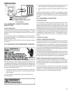
2. Identify the leads and using a Megger, Hi-Potential Ground
Tester, or other suitable instrument which puts out a volt-
age between 300 and 1500 volts, check for a ground sepa-
rately between each of the three leads and ground (such
as an unpainted tube on the compressor). Do not use a
low voltage output instrument such as a volt-ohmmeter.
3. If a ground is indicated, then carefully remove the compres-
sor terminal protective cover and inspect for loose leads or
insulation breaks in the lead wires.
4. If no visual problems indicated, carefully remove the leads
at the compressor terminals.
Carefully retest for ground, directly between compressor
terminals and ground.
5. If ground is indicated, replace the compressor.
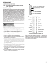
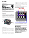
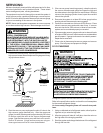
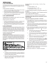
S-17C UNLOADER TEST PROCEDURE
A nominal 24-volt direct current coil activates the internal
unloader solenoid. The input control circuit voltage must be 18
to 28 volt ac. The coil power requirement is 20 VA. The exter-
nal electrical connection is made with a molded plug assem-
bly. This plug contains a full wave rectifier to supply direct
current to the unloader coil.
UNLOADER SOLENOID
(Molded Plug)
Unloader Test Procedure
If it is suspected that the unloader is not working, the
following methods may be used to verify operation.
1. Operate the system and measure compressor current.
Cycle the unloader ON and OFF at 10 second intervals.
The compressor amperage should go up or down at least
25 percent.
2. If step one does not give the expected results shut unit off.
Apply 18 to 28 volt ac to the unloader molded plug leads
and listen for a click as the solenoid pulls in. Remove power
and listen for another click as the unloader returns to its
original position.
3. If clicks can’t be heard, shut off power and remove the con-
trol circuit molded plug from the compressor and measure
the unloader coil resistance. The resistance should be 32
to 60 ohms, depending on compressor temperature.
4. Next check the molded plug.
A. Voltage check: Apply control voltage to the plug wires
(18 to 28 volt ac). The measured dc voltage at the
female connectors in the plug should be around 15
to 27 vdc.
B. Resistance check: Measure the resistance from the
end of one molded plug lead to either of the two
female connectors in the plug. One of the connec-
tors should read close to zero ohms while the other
should read infinity. Repeat with other wire. The same
female connector as before should read zero while
the other connector again reads infinity. Reverse
polarity on the ohmmeter leads and repeat. The fe-
male connector that read infinity previously should
now read close to zero ohms.
C. Replace plug if either of these test methods doesn’t
show the desired results.
S-17D OPERATION TEST
If the voltage, capacitor, overload and motor winding test fail to
show the cause for failure:
WARNING
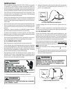
1. Remove unit wiring from disconnect switch and wire a test
cord to the disconnect switch.
NOTE: The wire size of the test cord must equal the line wire
size and the fuse must be of the proper size and type.
2. With the protective terminal cover in place, use the three
leads to the compressor terminals that were disconnected
at the nearest point to the compressor and connect the
common, start and run clips to the respective leads.
3. Connect good capacitors of the right MFD and voltage rat-
ing into the circuit.
4. With power ON, close the switch.
WARNING
LINE VOLTAGE NOW PRESENT.
A. If the compressor starts and continues to run, the
cause for failure is somewhere else in the system.
B. If the compressor fails to start - replace.