


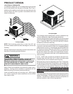

SYSTEM OPERATION
17
*PH15[24-60]M41*
APH15 M Series ECM equipped models only:
With the thermostat set to the emergency heat position and
a call for 2nd stage heat, R to W1 will be energized. This will
energize the electric heat sequencers and also energize W1
on the Variable Speed Terminal Board to start the indoor
blower motor. When the normally open contacts of the heat
sequencers close, this will energize the electric resistance
heat.
GPH15 M Series X13 equipped models only:
With the thermostat set to the emergency heat position and
a call for 2nd stage heat, R to W1 will be energized. This will
energize the electric heat sequencers and the GE X13
TM
motor. The electric heat will be energized through the nor-
mally open contacts of the electric heat sequencers. The
indoor blower will be energized through W from the thermo-
stat.
DEFROST CYCLE
Package Heat Pumps
The defrosting of the outdoor coil is jointly controlled by the
defrost control board and the defrost thermostat.
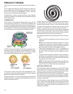
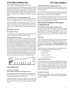
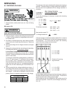
Solid State Defrost Control
During operation the power to the circuit board is controlled
by a temperature sensor, which is clamped to a feeder tube
entering the outdoor coil. Defrost timing periods of 30, 60, or
90 minutes may be selected by connecting the circuit board
jumper to 30, 60, or 90 respectively. Accumulation of time for
the timing period selected starts when the sensor closes
(approximately 34° F), and when the room thermostat calls
for heat. At the end of the timing period, the unit’s defrost
cycle will be initiated provided the sensor remains closed.
When the sensor opens (approximately 60° F), the defrost
cycle is terminated and the timing period is reset. If the de-
frost cycle is not terminated due to the sensor temperature,
a ten minute override interrupts the unit’s defrost period.
CY W2 R R DFT
TEST
DF1
DF2
JUMPER WIRE
90
60
30
A
FAN OPERATION
Continuous Fan Mode
APH15 M Series ECM equipped models only:
If the thermostat calls for continuous fan, the indoor blower
will be energized through the VSTB at 30% of selected sec-
ond stage cooling speed on APH15 units.
If the thermostat is not calling for heat or cool, and the fan
switch on the thermostat is returned to the automatic posi-
tion, the fan will stop after a 60 second delay on APH15
units.
GPH15 M Series X13 equipped models only:
If the thermostat calls for continuous fan, the indoor blower
will be energized from the G terminal of the thermostat to the
X13 blower motor.
If a call for heat or cool occurs during a continuous fan call,
the GE X13
TM
motor will always recognize the call for the
highest speed and ignore the lower speed call.
If the thermostat is not calling for heat or cool, and the fan
switch on the thermostat is returned to the automatic posi-
tion, the fan will stop after the programmed 60 second off
delay on units with the GE X13
TM
motor.
AIRFLOW ADJUSTMENTS FOR INDOOR
BLOWER MOTOR
APH15 M Series ECM equipped models only:
Dip switch 4 must be set to ON for APH1524- 36. Dip switch
4 must be set to OFF for 2-stage compressor models
APH1548-60. Dip switch 4 ON energizes Y1 signal to the
ECM motor anytime Y/Y2 is energized. The indoor motor
will not operate properly if switch is not set correctly for the
model.
ECM Motor
The ECM control board is factory set with the dip switch #4
in the “ON” position for single stage units and to the "OFF"
position for the 2 stage units. All other dip switches are fac-
tory set in the “OFF” position. For most applications, the
settings are to be changed according to the electric heat
size.
The ECM motor provides many features not available on the
traditional PSC motor. These features include:
• Improved Efficiency
• Constant CFM
• Soft Start and Stop
• Improved Humidity Control
Motor Speed Adjustment
Each ECM blower motor has been preprogrammed for opera-
tion at 4 distinct airflow levels when operating in Cooling/
Heat Pump mode or Electric Heat mode. These 4 distinct
levels may also be adjusted slightly lower or higher if de-
sired. The adjustment between levels and the trim adjust-
ments are made by changing the dip switch(s) either to an
"OFF" or "ON" position.
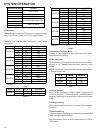
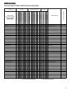
Dip Switch Functions
The ECM motor has an electronic control that contains eight
(8) 2-position dip switches. The function of these dip switches
is shown in Table 1.