


18
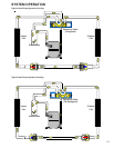
SYSTEM OPERATION
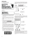
Dip Switch Number Function
1
2
3N/A
4 Indoor Thermostat
5
6
7
8
Cooling & Heat Pump CFM
CFM Trim Adjust
Electric Heat
Table 1
CFM Delivery
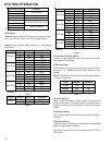
Tables 2 and 4 show the CFM output for dip switch combi-
nations 1-2 (Electric Heat), and 5-6 (Cooling/Heating).
Tables 3 shows the dip switch settings for 1 and 2-stage
thermostats.
Model Switch 1 Switch 2 Electric Heat CFM
OFF OFF
1050
(F)
ON OFF 950
OFF ON 825
ON ON 700
OFF OFF
1250
(F)
ON OFF 1100
OFF ON 1000
ON ON 800
OFF OFF
1800
(F)
ON OFF 1700
OFF ON 1400
ON ON 1225
OFF OFF
2000
(F)
ON OFF 1800
OFF ON 1600
ON ON 1400
APH1536
APH1548
APH1524
APH1560
(F)
Factory
Table 2
Model Switch 3 Switch 4 Thermostat
N/A ON 1-Stage
N/
A
OFF 2-Stage
APH15**
Table 3
Model Switch 5 Switch 6 Cooling/HP CFM
OFF OFF
1050
(F)
ON OFF 950
OFF ON 825
ON ON 700
OFF OFF
1250
(F)
ON OFF 1100
OFF ON 1000
ON ON 800
OFF OFF
1800
(F)
ON OFF 1700
OFF ON 1400
ON ON 1225
OFF OFF
2000
(F)
ON OFF 1800
OFF ON 1600
ON ON 1400
APH1536
APH1548
APH1524
APH1560
(F)
Factory
Table 4
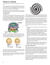
Thermostat “Fan Only” Mode
During Fan Only Operations, the CFM output is 30% of the
high stage cooling setting.
CFM Trim Adjust
Minor adjustments can be made through the dip switch com-
bination of 7-8. Table 5 shows the switch position for this
feature.
NOTE: The airflow will not make the decreasing adjustment
in Electric Heat mode.
CFM Switch 7 Switch 8
+10% ON OFF
Normal OFF OFF
-15% OFF ON
Table 5
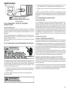
Humidity Control
When using a Humidistat (normally closed), cut jumper PJ6
on the control board. The Humidistat will only affect both low
stage and high stage cooling airflow by adjusting the Airflow
to 85%.
Two Stage Heating
When using staged electric heat, cut jumper PJ4 on the con-
trol board.
Thermostat Wiring
Use thermostat wiring diagrams provided with the thermostat
when making these connections.
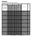
See Specification Sheet for APH model series for CFM vs
ESP tables.