


SERVICING
36
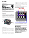
NOTE: R410A should be drawn out of the storage container or
drum in liquid form due to its fractionation properties, but should
be "Flashed" to its gas state before entering the system. There
are commercially available restriction devices that fit into the
system charging hose set to accomplish this. DO NOT charge
liquid R410A into the compressor.
4. With the system still running, close the valve on the charg-
ing cylinder. At this time, you may still have some liquid
refrigerant in the charging cylinder hose and will definitely
have liquid in the liquid hose. Reseat the liquid line core.
Slowly open the high side manifold valve and transfer the
liquid refrigerant from the liquid line hose and charging cyl-
inder hose into the suction service valve port. CAREFUL:
Watch so that liquid refrigerant does not enter the com-
pressor.
Final Charge Adjustment
The outdoor temperature must be 60°F or higher. Set the room
thermostat to COOL, fan switch to AUTO, and set the tem-
perature control well below room temperature.
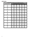
After system has stabilized per startup instructions, compare
the operating pressures and outdoor unit amp draw to the num-
bers listed in the technical manual. If pressures and amp draw
are too low, add charge. If pressures and amp draw are too
high, remove charge. Check subcooling and superheat as de-
tailed in the following section.
5. With the system still running, remove hose and reinstall
both valve caps.
6. Check system for leaks.
Due to their design, Scroll compressors are inherently more
tolerant of liquid refrigerant.
NOTE: Even though the compressor section of a Scroll com-
pressor is more tolerant of liquid refrigerant, continued flood-
back or flooded start conditions may wash oil from the bearing
surfaces causing premature bearing failure.
S-104 CHECKING COMPRESSOR
EFFICIENCY
The reason for compressor inefficiency is broken or damaged
suction and/or discharge valves, or scroll flanks on Scroll com-
pressors, reducing the ability of the compressor to pump re-
frigerant vapor.
The condition of the valves or scroll flanks is checked in the
following manner.
1. Attach gauges to the high and low side of the system.
2. Start the system and run a Cooling Performance Test.
If the test shows-
⇒ Below normal high side pressure.
⇒
Above normal low side pressure.
⇒
Low temperature difference across coil.
⇒ Low amp draw at compressor.
-and the charge is correct. The compressor is faulty - replace
the compressor.
S-105 THERMOSTATIC EXPANSION VALVE
The expansion valve is designed to control the rate of liquid
refrigerant flow into an evaporator coil in exact proportion to the
rate of evaporation of the refrigerant in the coil. The amount of
refrigerant entering the coil is regulated since the valve responds
to temperature of the refrigerant gas leaving the coil (feeler bulb
contact) and the pressure of the refrigerant in the coil. This
regulation of the flow prevents the return of liquid refrigerant to
the compressor.
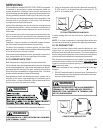
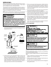
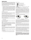
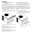
The illustration below shows typical heatpump TXV/check valve
operation in the heating and cooling modes.
COOLING HEATING
TXV VALVES
Some TXV valves contain an internal check valve thus eliminat-
ing the need for an external check valve and bypass loop. The
three forces which govern the operation of the valve are: (1) the
pressure created in the power assembly by the feeler bulb, (2)
evaporator pressure, and (3) the equivalent pressure of the su-
perheat spring in the valve.
0% bleed type expansion valves are used on indoor and out-
door coils. The 0% bleed valve will not allow the system pres-
sures (High and Low side) to equalize during the shut down
period. The valve will shut off completely at approximately 100
PSIG.
30% bleed valves used on some other models will continue to
allow some equalization even though the valve has shut-off
completely because of the bleed holes within the valve. This
type of valve should not be used as a replacement for a 0%
bleed valve, due to the resulting drop in performance.
The bulb must be securely fastened with two straps to a clean
straight section of the suction line. Application of the bulb to a
horizontal run of line is preferred. If a vertical installation can-
not be avoided, the bulb must be mounted so that the capillary
tubing comes out at the top.
THE VALVES PROVIDED BY GOODMAN ARE DESIGNED
TO MEET THE SPECIFICATION REQUIREMENTS FOR OP-
TIMUM PRODUCT OPERATION. DO NOT USE SUBSTI-
TUTES.