


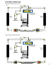
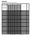

SERVICING
27
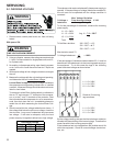
S-16 CHECKING MOTORS
S-16B CHECKING FAN AND BLOWER MOTOR
(ECM MOTORS)
APH15 M Series Only
An ECM is an Electronically Commutated Motor which offers
many significant advantages over PSC motors. The ECM has
near zero rotor loss, synchronous machine operation, variable
speed, low noise, and programmable air flow. Because of the
sophisticated electronics within the ECM motor, some techni-
cians are intimated by the ECM motor; however, these fears
are unfounded. GE offers two ECM motor testers, and with a
VOM meter, one can easily perform basic troubleshooting on
ECM motors. An ECM motor requires power (line voltage) and
a signal (24 volts) to operate. The ECM motor stator contains
permanent magnet. As a result, the shaft feels "rough" when
turned by hand. This is a characteristic of the motor, not an
indication of defective bearings.
WARNING
LINE VOLTAGE NOW PRESENT.
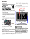
1. Disconnect the 5-pin connector from the motor.
2. Using a volt meter, check for line voltage at terminals #4 &
#5 at the power connector. If no voltage is present:
3. Check the unit for incoming power See section S-1.
4. If line voltage is present, reinsert the 5-pin connector and
remove the 16-pin connector.
5. Check for signal (24 volts) at the transformer.
6. Check for signal (24 volts) from the thermostat to the "G"
terminal at the 16-pin connector.
7. Using an ohmmeter, check for continuity from the #1 & #3
(common pins) to the transformer neutral or "C" thermostat
terminal. If you do not have continuity, the motor may func-
tion erratically. Trace the common circuits, locate and re-
pair the open neutral.
8. Set the thermostat to "Fan-On". Using a voltmeter, check
for 24 volts between pin # 15 (G) and common.
9. Disconnect power to compressor. Set thermostat to call
for cooling. Using a voltmeter, check for 24 volts at pin # 6
and/or #14.
10. Set the thermostat to a call for heating. Using a voltmeter,
check for 24 volts at pin #2 and/or #11.
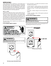
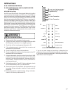
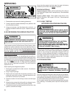
1
2
3
4
5
Lines 1 and 2 will be connected
for 12OVAC Power Connector
applications only
Gnd
AC Line Connection
AC Line Connection
}
11
19
2
3
4
5
6
7
816
15
14
13
12
10
OUT - OUT +
A
DJUST +/-
G (FAN)
Y1 Y/Y2
COOL
EM Ht/W2
DELAY
24 Vac (R)
COMMON2
HEAT
W/W1
BK/PWM (SPEED)
COMMON1 O (REV VALVE)
16-PIN ECM HARNESS CONNECTOR
If you do not read voltage and continuity as described, the
problem is in the control or interface board, but not the motor.
If you register voltage as described , the ECM power head is
defective and must be replaced.