


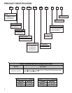

PRODUCT DESIGN
13
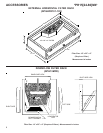
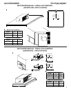
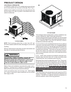
LOCATION & CLEARANCES
In installations where the unit is installed above ground level
and not serviceable from the ground (Example: Roof Top in-
stallations) the installer must provide a service platform for the
service person with rails or guards in accordance with local
codes or ordinances.
*PH15[24-60]M41*
NOTE: Roof overhang should be no more than 36" and
provisions made to deflect the warm discharge air out from the
overhang.
Minimum clearances are required to avoid air recirculation and
keep the unit operating at peak efficiency.
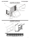
WARNING
TO PREVENT POSSIBLE DAMAGE, THE UNIT SHOULD
REMAIN IN AN UPRIGHT POSITION DURING ALL
RIGGING AND MOVING OPERATIONS. TO FACILITATE
LIFTING AND MOVING IF A CRANE IS USED, PLACE
THE UNIT IN AN ADEQUATE CABLE SLIDE.
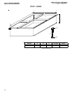
Refer to Roof curb Installation Instructions for proper curb in-
stallation. Curbing must be installed in compliance with the
National Roofing Contractors Association Manual.
Lower unit carefully onto roof mounting curb. While rigging
unit, center of gravity will cause condenser end to be lower
than supply air end.
*PH15[24-60]M4*
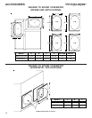
*PH Package Units are designed for outdoor installations only
in either residential or light commercial applications.
The connecting ductwork (Supply and Return) can be connected
for horizontal discharge airflow. In the down discharge applica-
tions, a matching Roof Curb (PGC101/102/103) is recom-
mended for horizontal models only.
A return air filter must be installed behind the return air grille(s)
or provision must be made for a filter in an accessible location
within the return air duct. An internal filter rack (GPH13MFR102
& 103) and an external filter rack (GPGHFR101-103) are also
available as accessories. The minimum filter area should not
be less than those sizes listed in the Specification Section.
Under no circumstances should the unit be operated without
return air filters.
A 3/4" - 14 NPT drain connector is provided for removal of con-
densate water from the indoor coil. In order to provide proper
condensate flow, do not reduce the drain line size.
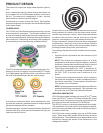
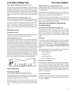
Refrigerant flow control is achieved by use of TXV. These mod-
els use the FasTest Access Fitting System, with a saddle that
is either soldered to the suction and liquid lines or is fastened
with a locking nut to the access fitting box (core) and then
screwed into the saddle. Do not remove the core from the
saddle until the refrigerant charge has been removed.
Failure to do so could result in property damage or per-
sonal injury.
The single phase units use permanent split capacitors (PSC)
design compressors. Starting components are therefore not
required. A low MFD run capacitor assists the compressor to
start and remains in the circuit during operation.
Roof Curb