


SERVICING
37
S-106 OVERFEEDING
Overfeeding by the expansion valve results in high suction pres-
sure, cold suction line, and possible liquid slugging of the com-
pressor.
If these symptoms are observed:
1. Check for an overcharged unit by referring to the cooling
performance charts in the servicing section.
2. Check the operation of the power element in the valve as
explained in S-110 Checking Expansion Valve Operation.
3. Check for restricted or plugged equalizer tube.
S-107 UNDERFEEDING
Underfeeding by the expansion valve results in low system
capacity and low suction pressures.
If these symptoms are observed:
1. Check for a restricted liquid line or drier. A restriction will
be indicated by a temperature drop across the drier.
2. Check the operation of the power element of the valve as
described in S-110 Checking Expansion Valve Operation.
S-108 SUPERHEAT
The expansion valves are factory adjusted to maintain 15 to 18
degrees superheat of the suction gas. Before checking the
superheat or replacing the valve, perform all the procedures
outlined under Air Flow, Refrigerant Charge, Expansion Valve -
Overfeeding, Underfeeding. These are the most common
causes for evaporator malfunction.
CHECKING SUPERHEAT
Refrigerant gas is considered superheated when its tempera-
ture is higher than the saturation temperature corresponding to
its pressure. The degree of superheat equals the degrees of
temperature increase above the saturation temperature at ex-
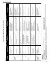
isting pressure. See Temperature - Pressure Chart on follow-
ing pages.
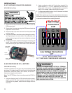
CAUTION
1. Run system at least 10 minutes to allow pressure to sta-
bilize.
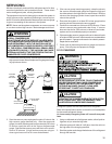
2. Temporarily install thermometer on suction (large) line
near suction line service valve with adequate contact and
insulate for best possible reading.
3. Refer to the superheat table provided for proper system
superheat. Add charge to lower superheat or recover
charge to raise superheat.
Superheat Formula = Suct. Line Temp. - Sat. Suct. Temp.
EXAMPLE:
a. Suction Pressure = 143
b. Corresponding Temp. °F. = 50
c. Thermometer on Suction Line = 66°F.
To obtain the degrees temperature of superheat, subtract 50.0
from 66.0°F.
The difference is 16° Superheat. The 16° Superheat would fall
in the ± range of allowable superheat.
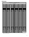
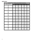
See R410A Pressure vs. Temperature chart on page 40.
SUPERHEAT AND SUBCOOLING ADJUSTMENT ON TXV
APPLICATIONS
Single Speed Application (*PH1524**-*PH1536**)
1. Purge gauge lines. Connect service gauge manifold to
access fittings. Run system at least 10 minutes to allow
pressure to stabilize.
2. Temporarily install thermometer on liquid (small) line near
liquid line access fitting with adequate contact and insu-
late for best possible reading.
3. Check subcooling and superheat. Systems with TXV ap-
plication should have a subcooling of 10
+ 2°F and super-
heat of 15 to 18ºF.
a. If subcooling and superheat are low, adjust TXV to
15 - 18ºF then check subcooling.
b. If subcooling is low and superheat is high, add charge
to raise subcooling to10 ± 2ºF then check super-
heat.
c. If subcooling and superheat are high, adjust TXV
valve to 15 - 18ºF then check subcooling.
d. If subcooling is high and superheat is low, adjust
TXV valve to 15 to 18ºF superheat and remove
charge to lower the subcooling to 10 ± 2ºF.
The TXV should NOT be adjusted at light load conditions
55º to 60ºF, under such conditions only the subcooling
can be evaluated. This is because suction pressure is
dependent on indoor airflow, and wet bulb temperature.
NOTE: Do NOT adjust charge based on suction pressure
unless there is a gross undercharge.
4. Disconnect manifold set. Installation is complete.