


16
SYSTEM OPERATION
through the magnetic holding coils of the compressor
contactor and fan motor for models with X13 motors and
Variable Speed Terminal Board (VSTB) for models with ECM
motors.
.
This draws in the normally open contact of the contactor,
starting the compressor and condenser fan motors. At the
same time, energizing the X13 motor for models so equipped
and energizing the VSTB for ECM equipped models, starting
the indoor fan motor.
When the thermostat is satisfied, it opens its contacts, break-
ing the low voltage circuit from R to Y & G, causing the com-
pressor contactor to open, and de-energizing the indoor blower
motor, shutting down the system.
If the room thermostat fan selector switch should be set to
the "on" position, then the indoor blower would run continu-
ous rather than cycling with the compressor.
APH and GPH models energize the reversing valve through
the "O" circuit in the room thermostat. Therefore, the revers-
ing valve remains energized as long as the thermostat sub-
base is in the cooling position.
HEATING CYCLE
*PH15**M41* Heat Pump Units
On a call for first stage heat, the contacts of the room ther-
mostat close. This energizes terminals R to Y and R to G,
the low voltage circuit to the contactor is completed starting
the compressor and outdoor fan motor. This also energizes
the indoor blower through the VSTB on delay on APH15 M
series units, and instantly on the GPH15 M series units with
the GE X13
TM
motor.
When the thermostat is satisfied, breaking the circuit be-
tween R to Y and R to G, the compressor and outdoor fan
motor will stop. The indoor blower will stop after the 60 sec-
ond off delay on the APH15 M series units, and after the
programmed 60 second off delay on GPH15 M series units
with the GE X13
TM
motor. .
When auxiliary electric heaters are used, a two stage heat-
ing two stage cooling thermostat would be installed.
Should the second stage heating contacts in the room ther-
mostat close, which would be wired to W1 at the unit low
voltage connections, this would energize the coil(s) of the
electric heat relay(s). Contacts within the relay(s) will close,
bringing on the electric resistance heaters.
If auxiliary electric heaters should be used, they may be con-
trolled by outdoor thermostats (OT18-60A or OT/EHR18-60A).
Emergency Heat Mode (Heat Pumps)
NOTE: The following only applies if the unit has an approved
electric heat kit installed for auxiliary heating.
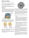
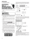
COOLING
The refrigerant used in the system is R-410A. It is a clear,
colorless, non-toxic and non-irritating liquid. R-410A is a 50:50
blend of R-32 and R-125. The boiling point at atmospheric
pressure is -62.9°F.
A few of the important principles that make the refrigeration
cycle possible are: heat always flows from a warmer to a
cooler body. Under lower pressure, a refrigerant will absorb
heat and vaporize at a low temperature. The vapors may be
drawn off and condensed at a higher pressure and tempera-
ture to be used again.
The indoor evaporator coil functions to cool and dehumidify
the air conditioned spaces through the evaporative process
taking place within the coil tubes.
Heat is continually being transferred to the cool fins and tubes
of the indoor evaporator coil by the warm system air. This
warming process causes the refrigerant to boil. The heat re-
moved from the air is carried off by the vapor.
As the vapor passes through the last tubes of the coil, it
becomes superheated. That is, it absorbs more heat than is
necessary to vaporize it. This is assurance that only dry gas
will reach the compressor. Liquid reaching the compressor
can weaken or break compressor valves.
The compressor increases the pressure of the gas, thus add-
ing more heat, and discharges hot, high pressure superheated
gas into the outdoor condenser coil.
In the condenser coil, the hot refrigerant gas, being warmer
than the outdoor air, first loses its superheat by heat trans-
ferred from the gas through the tubes and fins of the coil. The
refrigerant now becomes saturated, part liquid, part vapor and
then continues to give up heat until it condenses to a liquid
alone. Once the vapor is fully liquefied, it continues to give up
heat which subcools the liquid, and it is ready to repeat the
cycle.
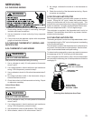
HEATING
The heating portion of the refrigeration cycle is similar to the
cooling cycle. By de-energizing the reversing valve solenoid
coil, the flow of the refrigerant is reversed. The indoor coil
now becomes the condenser coil, and the outdoor coil be-
comes the evaporator coil.
The check valve in the TXV at the indoor coil will open by the
flow of refrigerant letting the now condensed liquid refrigerant
bypass the indoor expansion device. The check valve in the
TXV at the outdoor coil will be forced closed by the refrigerant
flow, thereby utilizing the outdoor expansion device.
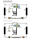
COOLING CYCLE
On heat pump models, when the thermostat is switched to
cool, this completes a circuit from R to O energizing the
reversing valve solenoid. When the contacts of the room
thermostat close making terminals R to Y & G, the low voltage
circuit of the transformer is completed. Current now flows
SYSTEM OPERATION *PH15[24-60]M41*