


SERVICING
33
S-18 TESTING CRANKCASE HEATER
Note: Not all compressors use crankcase heaters.
The crankcase heater must be energized a minimum of four
(4) hours before the compressor is operated.
Crankcase heaters are used to prevent migration or accumula-
tion of refrigerant in the compressor crankcase during the off
cycles and prevents liquid slugging or oil pumping on start up.
Scroll Compressors are not equipped with a crankcase heat-
ers.
A crankcase heater will not prevent compressor damage due
to a floodback or over charge condition.
WARNING
DISCONNECT POWER SUPPLY BEFORE SERVICING.
1. Disconnect the heater lead wires.
2. Using an ohmmeter, check heater continuity - should test
continuous, if not, replace.
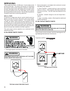
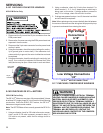
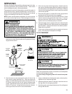
S-21 CHECKING REVERSING VALVE AND
SOLENOID
Occasionally the reversing valve may stick in the heating or
cooling position or in the mid-position.
When stuck in the mid-position, part of the discharge gas from
the compressor is directed back to the suction side, resulting
in excessively high suction pressure. An increase in the suc-
tion line temperature through the reversing valve can also be
measured. Check operation of the valve by starting the sys-
tem and switching the operation from COOLING to HEATING
cycle.
If the valve fails to change its position, test the voltage (24V) at
the valve coil terminals, while the system is on the COOLING
cycle.
If no voltage is registered at the coil terminals, check the op-
eration of the thermostat and the continuity of the connecting
wiring from the "O" terminal of the thermostat to the unit.
If voltage is registered at the coil, tap the valve body lightly
while switching the system from HEATING to COOLING, etc.
If this fails to cause the valve to switch positions, remove the
coil connector cap and test the continuity of the reversing valve
solenoid coil. If the coil does not test continuous - replace it.
If the coil test continuous and 24 volts is present at the coil
terminals, the valve is inoperative - replace it.
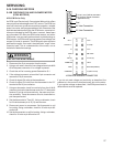
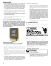
S-24 TESTING DEFROST CONTROL
To check the defrost control for proper sequencing, proceed as
follows: With power ON; unit not running.
1. Jumper defrost thermostat by placing a jumper wire across
the terminals "DFT" and "R" at defrost control board.
2. Connect jumper across test pins on defrost control board.
3. Set thermostat to call for heating. System should go into
defrost within 21 seconds.
4. Immediately remove jumper from test pins.
5. Using VOM check for voltage across terminals "C & O".
Meter should read 24 volts.
6. Using VOM check for voltage across fan terminals DF1
and DF2 on the board. You should read line voltage (208-
230 VAC) indicating the relay is open in the defrost mode.
7. Using VOM check for voltage across "W2 & C" terminals
on the board. You should read 24 volts.
8. If not as above, replace control board.
9. Set thermostat to off position and disconnect power before
removing any jumpers or wires.
NOTE: Remove jumper across defrost thermostat before re-
turning system to service.
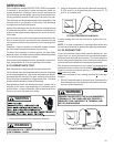
S-25 TESTING DEFROST THERMOSTAT
1. Install a thermocouple type temperature test lead on the
tube adjacent to the defrost control. Insulate the lead point
of contact.
2. Check the temperature at which the control closes its con-
tacts by lowering the temperature of the control. The de-
frost control should close at 34°F ± 5°F.
3. Check the temperature at which the control opens its con-
tacts by raising the temperature of the control. The defrost
control should open at 60°F ± 5°F.
4. If not as above, replace control.
S-50 CHECKING HEATER LIMIT CONTROL(S)
(OPTIONAL ELECTRIC HEATERS)
Each individual heater element is protected with an automatic
rest limit control connected in series with each element to
prevent overheating of components in case of low airflow. This
limit control will open its circuit at approximately 150°F. to
160°F and close at approximately 110°F.
WARNING
DISCONNECT ELECTRICAL POWER SUPPLY.
1. Remove the wiring from the control terminals.
2. Using an ohmmeter test for continuity across the normally
closed contacts. No reading indicates the control is open
- replace if necessary. Make sure the limits are cool before
testing.
IF FOUND OPEN - REPLACE - DO NOT WIRE AROUND.
S-52 CHECKING HEATER ELEMENTS
Optional electric heaters may be added, in the quantities shown
in the spec sheet for each model unit, to provide electric resis-
tance heating. Under no condition shall more heaters than the
quantity shown be installed.