


SERVICING
24
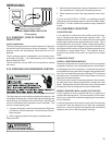
S-4 CHECKING TRANSFORMER AND
CONTROL CIRCUIT
A step-down transformer (208/240 volt primary to 24 volt sec-
ondary) is provided with each package unit. This allows ample
capacity for use with resistance heaters.
WARNING
1. Remove control panel cover or etc. to gain access to trans-
former.
With power ON:
WARNING
LINE VOLTAGE NOW PRESENT.
2. Using a voltmeter, check voltage across secondary voltage
side of transformer (R to C).
3. No voltage indicates faulty transformer, bad wiring, or bad
splices.
4. Check transformer primary voltage at incoming line voltage
connections and/or splices.
5 If line voltage is present at the primary voltage side of the
transformer and 24 volts is not present on the secondary
side, then the transformer is inoperative. Replace.
S-7 CHECKING CONTACTOR AND/OR
RELAYS
The compressor contactor and other relay holding coils are
wired into the low or line voltage circuits. When the control
circuit is energized the coil pulls in the normally open contacts
or opens the normally closed contacts. When the coil is de-
energized, springs return the contacts to their normal position.
WARNING
DISCONNECT POWER SUPPLY BEFORE SERVICING.
1. Remove the leads from the holding coil.
2. Using an ohmmeter, test across the coil terminals.
If the coil does not test continuous, replace the relay or con-
tactor.
S-8 CHECKING CONTACTOR CONTACTS
WARNING
DISCONNECT POWER SUPPLY BEFORE SERVICING.
SINGLE PHASE
1. Disconnect the wire leads from the terminal (T) side of the
contactor.
2. With power ON, energize the contactor.
WARNING
LINE VOLTAGE NOW PRESENT.
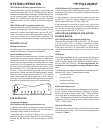
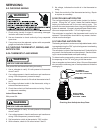
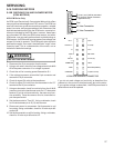
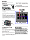
VOLT/OHM
METER
T1
T2
L1L2
CC
Ohmmeter for testing holding coil
Voltmeter for testing contacts
TESTING COMPRESSOR CONTACTOR
(Single Phase)
3. Using a voltmeter, test across terminals.
A. L1 to L2 - No voltage. Check breaker or fuses on main
power supply. If voltage present, proceed to step B.
B. T1 to T2 - Meter should read the same as L1 to L2 in
step A. If voltage readings are not the same as step A,
replace contactor.
THREE PHASE
Using a voltmeter, test across terminals:
A. L1-L2, L1-L3, and L2-L3 - If voltage is present, pro-
ceed to B. If voltage is not present, check breaker or
fuses on main power supply..
B. T1-T2, T1-T3, and T2-T3 - If voltage readings are not
the same as in "A", replace contactor.