


SERVICING
22
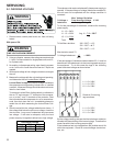
S-1 CHECKING VOLTAGE
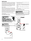
WARNING
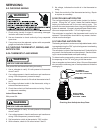
1. Remove doors, control panel cover, etc. from unit being
tested.
With power ON:
WARNING
LINE VOLTAGE NOW PRESENT.
2. Using a voltmeter, measure the voltage across terminals
L1 and L2 of the contactor for single phase units, and L3,
for 3 phase units.
3. No reading - indicates open wiring, open fuse(s) no power
or etc. from unit to fused disconnect service. Repair as
needed.
4. With ample voltage at line voltage connectors, energize
the unit.
5. Measure the voltage with the unit starting and operating,
and determine the unit Locked Rotor Voltage.
Locked Rotor Voltage is the actual voltage available at
the compressor during starting, locked rotor, or a stalled
condition. Measured voltage should be above minimum
listed in chart below.
To measure Locked Rotor Voltage attach a voltmeter to
the run "R" and common "C" terminals of the compres-
sor, or to the T
1
and T
2
terminals of the contactor. Start
the unit and allow the compressor to run for several sec-
onds, then shut down the unit. Immediately attempt to
restart the unit while measuring the Locked Rotor Volt-
age.
6. Should read within the voltage tabulation as shown. If
the voltage falls below the minimum voltage, check the
line wire size. Long runs of undersized wire can cause
low voltage. If wire size is adequate, notify the local
power company in regards to either low or high voltage.
Voltage Min. Max.
460 437 506
208/230 198 253
Unit Supply Voltage
Three phase units require a balanced 3 phase power supply to
operate. If the percentage of voltage imbalance exceeds 3%
the unit must not be operated until the voltage condition is
corrected.
Max. Voltage Deviation
% Voltage =
From Average Voltage X 100
Imbalance Average Voltage
To find the percentage of imbalance, measure the incoming
power supply.
L1 - L2 = 240V
L1 - L3 = 232V Avg. V = 710 = 236.7
L2 - L3 = 238V 3
Total 710V
To find Max. deviation: 240 - 236.7 = +3.3
232 - 236.7 = -4.7
238 - 236.7 = +1.3
Max deviation was 4.7V
% Voltage Imbalance = 4.7 = 1.99%
236.7
If the percentage of imbalance had exceeded 3%, it must be
determined if the imbalance is in the incoming power supply or
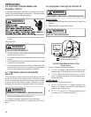
the equipment. To do this rotate the legs of the incoming
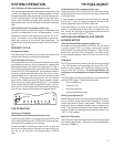
power and retest voltage as shown below.
L1
L2
L3
L3L2
L1
By the voltage readings we see that the imbalance rotated or
traveled with the switching of the incoming legs. Therefore the
power lies within the incoming power supply.
If the imbalance had not changed then the problem would lie
within the equipment. Check for current leakage, shorted mo-
tors, etc.
L1 - L2 = 240V
L1 - L3 = 227V
L2 - L3 = 238V
Rotate all 3 incoming
legs as shown.
L1 - L2 = 227V
L1 - L3 = 238V
L2 - L3 = 240V