


SERVICING
25
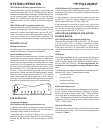
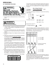
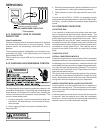
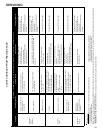
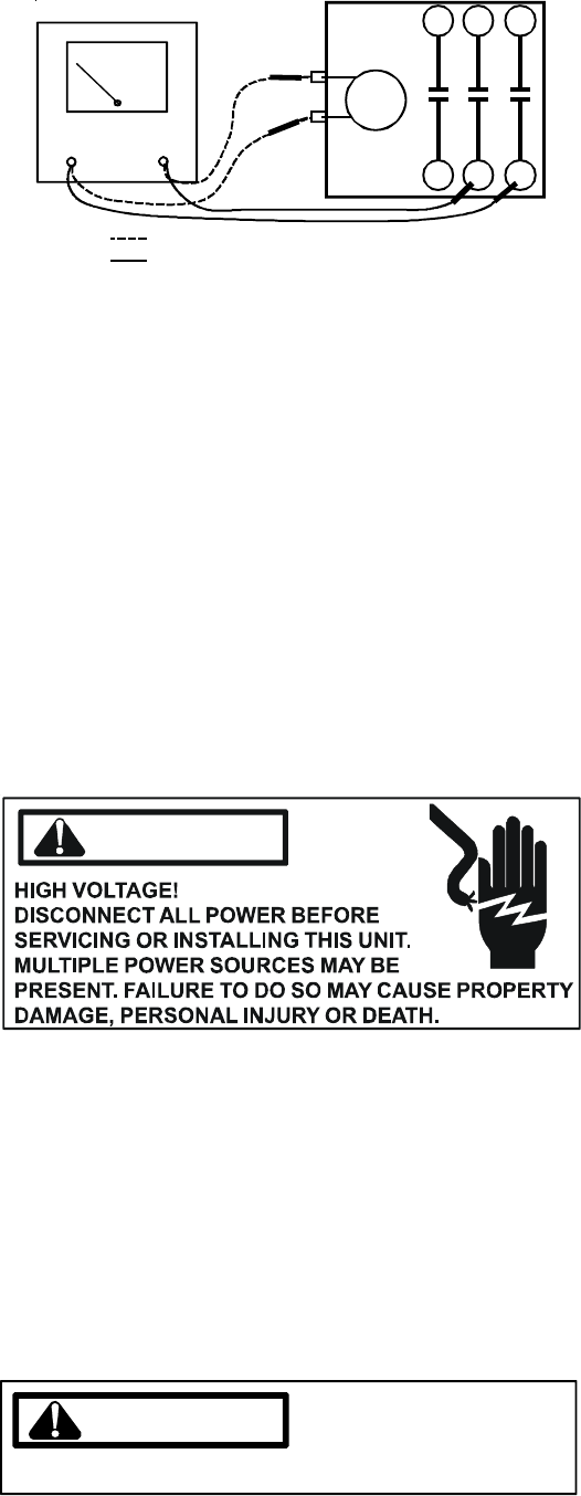
VOLT/OHM
METER
CC
Ohmmeter for testing holding coil
Voltmeter for testing contacts
T1
L1
T3
L3
T2
L2
TESTING COMPRESSOR CONTACTOR
(Three-phase)
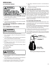
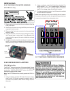
S-11 CHECKING LOSS OF CHARGE
PROTECTOR
(Heat Pump Models)
The loss of charge protector senses the pressure in the liquid
line and will open its contacts on a drop in pressure. The low
pressure control will automatically reset itself with a rise in
pressure.
The low pressure control is designed to cut-out (open) at ap-
proximately 50 PSIG. It will automatically cut-in (close) at
approximately 95 PSIG.
Test for continuity using a VOM and if not as above, replace
the control.
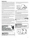
S-12 CHECKING HIGH PRESSURE CONTROL
WARNING
The high pressure control capillary senses the pressure in the
compressor discharge line. If abnormally high condensing pres-
sures develop, the contacts of the control open, breaking the
control circuit before the compressor motor overloads. This
control is automatically reset.
1. Using an ohmmeter, check across terminals of high pres-
sure control, with wire removed. If not continuous, the con-
tacts are open.
3. Attach a gauge to the dill valve port on the base valve.
With power ON:
WARNING
LINE VOLTAGE NOW PRESENT.
4. Start the system and place a piece of cardboard in front of
the condenser coil, raising the condensing pressure.
5. Check pressure at which the high pressure control cuts-
out.
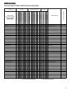
If it cuts-out at 610 PSIG ± 10 PSIG, it is operating normally
(See causes for high head pressure in Service Problem Analy-
sis Guide). If it cuts out below this pressure range, replace the
control.
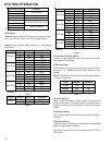
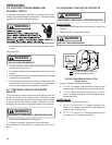
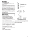
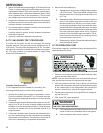
S-15 CHECKING CAPACITOR
CAPACITOR, RUN
A run capacitor is wired across the auxiliary and main wind-
ings of a single phase permanent split capacitor motor. The
capacitors primary function is to reduce the line current while
greatly improving the torque characteristics of a motor. This is
accomplished by using the 90° phase relationship between
the capacitor current and voltage in conjunction with the motor
windings so that the motor will give two phase operation when
connected to a single phase circuit. The capacitor also re-
duces the line current to the motor by improving the power
factor.
CAPACITOR, START
SCROLL COMPRESSOR MODELS
Hard start components are not required on Scroll compressor
equipped units due to a non-replaceable check valve located in
the discharge line of the compressor. However hard start kits
are available and may improve low voltage starting characteris-
tics. Only hard start kits approved by Goodman
®
or Copeland
should be used. "Kick Start" and/or "Super Boost" kits are not
approved start assist devices.
This check valve closes off high side pressure to the compres-
sor after shut down allowing equalization through the scroll
flanks. Equalization requires only about one or two seconds
during which time the compressor may turn backwards.
MODELS EQUIPPED WITH A HARD START DEVICE
A start capacitor is wired in parallel with the run capacitor to
increase the starting torque. The start capacitor is of the elec-
trolytic type, rather than metallized polypropylene as used in
the run capacitor.
A switching device must be wired in series with the capacitor
to remove it from the electrical circuit after the compressor
starts to run. Not removing the start capacitor will overheat the
capacitor and burn out the compressor windings.