


Instruction Manual
760007-A
July 2003
ii Contents Rosemount Analytical Inc. A Division of Emerson Process Management
Model NGA2000 PMD
5-0 REPLACEMENT PARTS......................................................................................................5-1
5-1 Matrix.....................................................................................................................................5-1
5-2 Replacement Parts................................................................................................................5-2
6-0 RETURN OF MATERIAL......................................................................................................6-1
6-1 Return Of Material .................................................................................................................6-1
6-2 Customer Service..................................................................................................................6-1
6-3 Training..................................................................................................................................6-1
7-0 APPENDIX A. MENU DISPLAYS.........................................................................................7-1
LIST OF ILLUSTRATIONS
Figure 1-1. Spherical Body in Non-Uniform Magnetic Field..................................................... 1-1
Figure 1-2. Trace Oxygen Detector Coulometric Principle........................................................ 1-2
Figure 2-1. Analyzer Module Installation Into Instrument Platform .......................................... 2-1
Figure 2-2. PMD Front Panel Connections .............................................................................. 2-4
Figure 2-3. PMD Back Panel Connections............................................................................... 2-4
Figure 2-4. Interconnection of Typical Gas Manifold to PMD Analyzer Module ...................... 2-5
Figure 2-5. PMD Wiring Diagram............................................................................................. 2-6
Figure 2-6. PMD Outline and Mounting Dimensions................................................................ 2-7
Figure 3-1. Run Mode Display ................................................................................................. 3-3
Figure 3-2. Main Menu Display ................................................................................................ 3-3
Figure 3-3. Basic Controls Menu.............................................................................................. 3-3
Figure 3-4. Expert Controls and Setup Menu........................................................................... 3-4
Figure 3-5. Technical Level Configuration Menu ..................................................................... 3-4
Figure 3-6. Typical Help Screen............................................................................................... 3-4
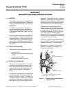
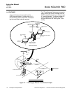
Figure 4-1. PMD Module – Major Components ....................................................................... 4-1
Figure 4-2. Module Fan Assembly ........................................................................................... 4-2
Figure 4-3. Detector Assembly................................................................................................. 4-3
LIST OF TABLES
Table 3-1. PMD Analyzer Module Alarms............................................................................... 3-2
Table 3-2. Calibration Range for Various Zero Based Operating Ranges ............................. 3-6
Table 3-3. Calibration Range for Various Suppressed Range Operations............................. 3-6
Table 3-4. Oxygen Equivalents of Common Gases.............................................................. 3-10