


Instruction Manual
760007-A
July 2003
2-2 Installation Rosemount Analytical Inc. A Division of Emerson Process Management
Model NGA2000 PMD
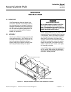
2-3 LOCATION
Install the Analyzer Module in a clean, non-
hazardous, weather protected, vibration free
location free from extreme temperature varia-
tions. For best results, either install the mod-
ule near the sample stream to minimize
sample transport time or supply a flow greater
than necessary and route only the appropriate
amount through the Analyzer Module.
Observing these requirements are critical.
Note the following:
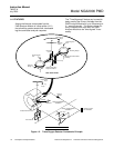
• Excessive vibration can cause a noisy
readout. To minimize vibration effects,
the detector/magnet assembly is envel-
oped in a shock-mounted compartment.
• The user should ensure, when making
any internal electrical connections, that
no cables are placed in contact with the
detector assembly or associated internal
sample inlet and outlet tubing.
• Magnetic susceptibilities and partial
pressures of gases vary with tempera-
ture. Permissible ambient temperature
range is 32°F to 113°F (0°C to 45°C).
• The interior of the Detector Assembly is
maintained at approximately 144°F
(62°C) by an electronically controlled
heater. Prior to entering the detector
assembly, the sample is heated in a
coiled tubing to match the detector's
temperature.
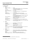
2-4 GASES
a. Requirements
Calibration Gases
Analyzer Module calibration requires the
establishment of zero and span calibra-
tion points. This requires a zero standard
gas to set the zero point span gas to es-
tablish a calibration point at or near the
upper range limit.
An oxygen-free gas, typically nitrogen, is
required for use as the zero standard gas.
Recommendations for span calibration
gases, bases on various operating
ranges, are tabulated in Table 3-4 on
page 3-10. Air (20.93% oxygen) can be
used as span gas regardless of the
ranges used for sampling, although very
low ranges may lose accuracy.
Sample Gas
Sample gas should be non-flammable.
Temperature
Sample temperature at the inlet should be
from 50°F to 150°F (10°C to 66°C). A
maximum entry temperature of 110°F
(43°C) is recommended to prevent cool-
ing of the sample and possible internal
condensation. Such condensation could
damage some components of the Ana-
lyzer Module. This recommendation can
be ignored if a thoroughly dry sample is
examined.
Pressure
Sample exhaust pressure limits are -5 to
10 psig (-345 to 690 hPa-gauge). Normal
operation is in the positive range, be-
tween 0 and 10 psig (0 and 690 hPa-
gauge). Negative gauge pressures are
not normally recommended, but may be
used in certain special applications.
To prevent over-pressurization, insert a
pressure relief valve into the sample inlet
line. A check valve should also be placed
in the outlet line if the Analyzer Module is
connected to a manifold associated with a
flare or other apparatus that does not op-
erate at atmospheric pressure.
The outlet port is commonly vented to the
atmosphere. Any change in barometric
pressure has a directly proportional effect
on the indicated percent of oxygen, and
should be neutralized through manual or
computer correction of data. Note the fol-
lowing example: