


Instruction Manual
760007-A
July 2003
2-6 Installation Rosemount Analytical Inc. A Division of Emerson Process Management
Model NGA2000 PMD
2-5 ELECTRICAL CONNECTIONS
NOTE
Electrical connections must be in compli-
ance with National Electrical Code
(ANSI/NFPA 70) and/or any applicable na-
tional or electrical codes.
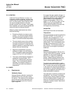
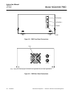
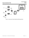
Two electrical connections are required on the
Analyzer Module; POWER and NETWORK.
See Figure 2-2 on page 2-4. On the Analyzer
Module, two NETWORK connections are
available, either of which is appropriate for : 1)
interconnection with Backplane of the Plat-
form (see Platform instruction manual) or 2)
"daisy chaining" with other NGA2000 compo-
nents.
Connect Analyzer Module POWER 24 VDC
power source, either the Platform or external
power source.
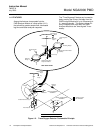
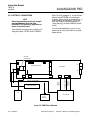
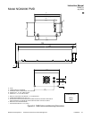
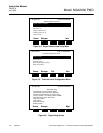
Figure 2-5. PMD Wiring Diagram
J5
J10
J14
J19
W1
J16
J20
J21 J22
J15
J12
J9
J17
J6
J7
J3
J2
J1
J4
COMPUTER ANALYSIS
BOARD
MAIN BOARD
J13
PRESSURE
COMPENSATION
BOARD
J11
FAN
FLOW
SENSOR
OPTICAL BENCH
LED SOURCE
ASSEMBLY
MAGNET HEATER AND
THERMAL CUTOFF
SENSOR
ASSEMBLY
PREAMP CABLE ASSEMBLY
FLOW SENSOR CABLE
CASE TEMP SENSOR