Instruction Manual
760007-A
July 2003
Rosemount Analytical Inc. A Division of Emerson Process Management Installation 2-1
Model NGA2000 PMD
SECTION 2
INSTALLATION
2-1 UNPACKING
If the Paramagnetic Analyzer Module is re-
ceived as a separate unit, carefully examine
the shipping carton and contents for signs of
damage. Immediately notify the shipping car-
rier if the carton or contents is damaged. Re-
tain the carton and packing material until all
components associated with the Analyzer
Module are operational.
2-2 ASSEMBLY
If the Analyzer Module requires assembly with
other components (e.g., the Platform and as-
sociated I/O Modules), do so at this time. Fol-
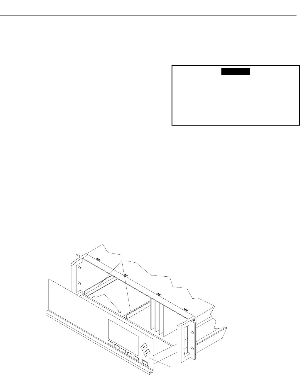
lowing the guides on the bottom left and
bottom center of the Platform, carefully slide
the Analyzer Module halfway into place.
WARNING
HAND INJURY HAZARD
Do not place hands or fingers in the Plat-
form front handles when front panel is
open. Dropping the front panel of the Plat-
form while hand or fingers are inside either
handle can cause serious injury.
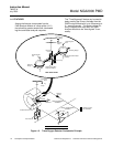
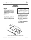
Lift the spring-loaded pins on the front of the
Analyzer Module, and carefully slide it the rest
of the distance. Secure the module in position
by releasing the pins, which seat in the avail-
able holes in the bottom of the case (see
Figure 2-1 below). If the module and Platform
are difficult to assemble, remove the module,
ensure the top cover of the module is firmly
seated on the hold-down screws, and repeat
the assembly procedure.
Install I/O Module(s) according to guidelines in
the I/O manual. After startup and calibration
have been performed, secure the front panel
with the six screws provided.
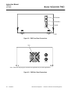
Figure 2-1. Analyzer Module Installation Into Instrument Platform
A
NALYZER MODULE GUIDES
PIN SEATS
DISENGAGED FRONT PANEL


