


www.desatech.com
111245-01C 9
-
This fireplace normally operates under 120
VAC/60 Hz line voltage. The electrical cord sup-
plied with your replace is ve feet in length. You
must locate replace within reach of a 120 volt
grounded electrical outlet. If not, you must install
an electrical outlet within reach of the replace
power cord. The GA3555 outlet accessory may
be used for built-in applications.
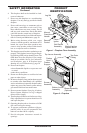
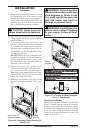
INSTALLATION CLEARANCES
WARNING: Maintain the
INSTALLATION
Continued
MINIMUM CLEARANCE TO
0" 16" 0"
Carefully follow the instructions below. This will
ensure safe installation.
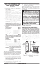
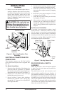
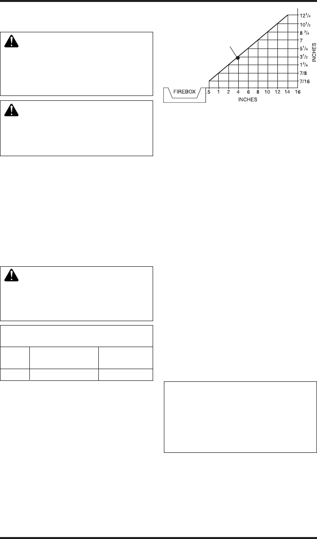
Minimum Clearances For Side
A. Clearances from the side of the fireplace
cabinet to any combustible material and wall
should follow diagram in Figure 5.
Example: The face of a mantel, bookshelf,
etc. is made of combustible material and
protrudes 3
1
/
2
" from the wall. This combus-
tible material must be 4" from the side of the
replace cabinet (see Figure 5).
B. Clearances from the top of the replace opening
to the ceiling should not be less than 42".
Figure 5 - Minimum Clearance for
Combustible to Wall
*Minimum 16" from Side Wall
*
Example
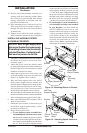
After unpacking replace (see Unpacking, page 4),
we suggest that you install your replace system
in the following sequence:
1.
Removal of replace oor assembly (required)
2. Electrical connections for power cord (re-
quired)
3. Relocating wall switch (optional)
4. Installing blower accessory (optional)
5.
Connecting replace to gas supply (required)
6. Checking gas connections (required)
7. Firebox installation, conventional or built-in
(required)
8. Installing brass perimeter trim (optional)
9. Installing replace hood (required)
10. Installing logs (required)
11. Installing replace screen (required)
Use the following instructions to complete
each step.
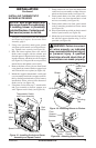
NOTICE:
-
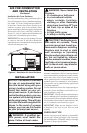
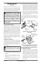
1. Remove replace screen. Remove two screws
that hold replace screen in place for shipping.
These screws are located near top of screen.
Discard screws. Lift replace screen up and
pull out to remove.
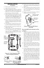
2. If logs are installed, carefully remove the logs
and set aside, noting the properly mounted
location of each.