


www.desatech.com
111245-01C 11
INSTALLATION
Continued
Note: If you choose to relocate the wall switch
assembly, do so before nal installation into a
mantel or recessing into a wall. If you are installing
an optional blower accessory, install it at the same
time you relocate the wall switch assembly.
CAUTION: The wall switch
-
wall of mantel or on wall to side
For Recessed Installation
If fireplace is to be recessed into a wall (see
Built-In Fireplace Installation, page 21), we
recommend mounting wall switch assembly to
left side of replace. The wall switch assembly
should be mounted approximately 12" from left
edge of replace and less than 60" from the oor.
IMPORTANT: Do not locate wall switch assembly
directly in front of wall stud - there must be room
behind wall board for wires from switch. If you
choose to locate wall switch assembly to right side
of replace, the length of the cord restricts you to
less than 6" from right edge of replace and less
than 48" from oor.
For Mantel Installation
If replace is to be installed into a mantel, (see
Conventional Fireplace Installation, page 20) the
wall switch assembly may be mounted on either
side of the mantel, facing to the side. Do not locate
wall switch assembly anywhere on the front face
of the mantel.
1. Determine the new location for the wall switch
assembly. The wires attached to switch are six
feet long.
2. Remove 2 screws securing plastic wall switch
assembly to bracket in replace lower cavity.
Save screws.
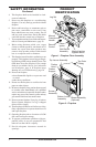
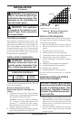
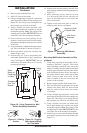
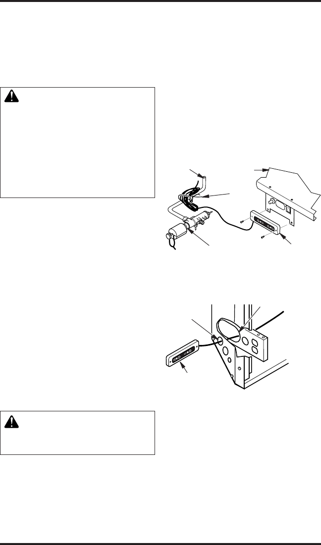
3. Remove wire tie holding coiled wire attached
to wall switch assembly (see Figure 8).
4. Remove wall switch assembly from bracket.
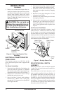
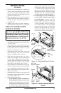
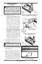
5. Carefully pass wall switch assembly and cord
through large elongated hole in rear of either
left or right oor support bracket, depending on
desired location of switch. Pass wall switch as-
sembly and cord through 1.5" diameter hole in
side of replace outer casing (see Figure 9).
6. Pull wall switch assembly and cord from
replace making sure wall switch assembly
will reach desired mounting location without
straining cord assembly.
If you are mounting wall switch assembly to a
wall, continue reading. If you are mounting your
wall switch assembly to the side of the mantel,
see page 12.
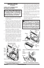
Figure 8 - Relocating Wall Switch
Assembly
Wall Switch
Assembly
Wire
Tie
Burner
Outlet
Tube
Gas Control
Valve
Firebox
Bottom
Figure 9 - Routing Wall Switch Assembly
Through Fireplace for Relocation
Wall Switch
Assembly
Hole in
Outer
Casing
Hole in Floor
Support Bracket
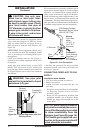
7. Create three openings on wall according to
Template 1, page 41. This is best done by
making a pattern to work with on your wall.
Carefully cut page 41/42 from manual and
tape paper template vertically onto wall at
preferred location. Pierce the paper at the cen-
ters of the 2 holes with a nail or sharp pencil,
leaving a mark on the wall. Do the same at
centers of the four circles near the corners of
the rectangle.