www.desatech.com
111245-01C14
9. Check to make sure that all electrical cords
are completely clear of the blower wheel
and that there are no other foreign objects in
blower wheel. Turn blower on and check for
operation. Turn blower off by rotating knob
fully counterclockwise before continuing.
CAUTION: Never touch the
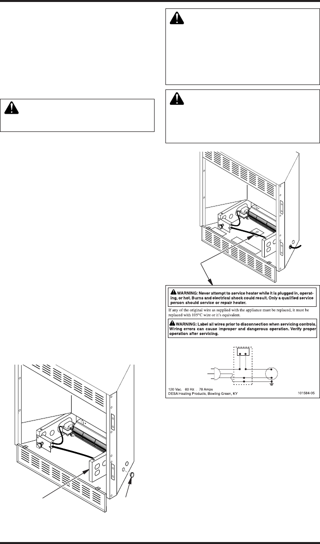
10. Peel off backing paper and stick supplied
wiring diagram decal near center of rebox
bottom (Figure 17).
11. If gas connections have been made and
checked, replace replace oor assembly.
Feed exible gas supply line into replace
base area while replacing replace oor as-
sembly. Make sure the entire exible gas line
is in replace base area.
IMPORTANT: Do not pick up replace oor
assembly by burners. This could damage
burners. Only handle base by grates. Note:
Be careful of all wires and components on
underside of oor assembly.
12. Reattach fireplace floor assembly with
screws removed in step 3 of Removing Fire-
place Screen and Floor Assembly, page 9.
Note: Discard the remaining hardware items.
After assembly, make sure all wires are com-
pletely clear of blower wheel.
13. Install logs (see Installing Logs, page 24 and
replace screen (see Installing Screen, page
25).
INSTALLATION
Continued
V
a
r
i
a
b
le
F
a
n
S
w
it
c
h
W
h
i
t
e
W
h
i
t
e
B
l
a
c
k
G
r
e
e
n
O
n
1
1
0
/
1
1
5
V
.
A
.
C
.
Blower
Moto
r
B
l
a
c
k
B
l
a
c
k
B
l
a
c
k
O
f
f
Wiring
Diagram
Figure 17 - Location of Wiring Diagram
Decal 3" from Blower
Light your gas appliance with the blower off. After
about 15 minutes, turn the blower on to deliver
heated air at the top louvers. The blower features
a variable control which allows you to select the
speed you desire. Note: Periodically check the
louvers of the rebox and remove any dust, dirt
or other obstructions.
Variable
Fan Switch
WhiteWhite
Black
Green
On
110/115
V.A.C.
Blower
Motor
Black
Black
Black
Off
Plastic
Bushing
Right Floor
Support Bracket
Figure 16 - Installing Plastic Bushing for
Power Cord
-
with this heater may result in


