Version 1.0b
13
STEP 2:
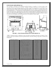
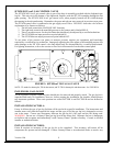
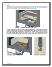
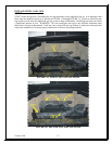
The ember tray and rear burner assembly are now ready for installation. This assembly includes steel tray
framing, the rear burner assembly, including the gas tube. Refer to FIGURE 7 to view the installation of
these parts. The installation is in the direction of the arrows shown in FIGURE 7.
FIGURE 7: BURNER INSTALLATION, STEP 2
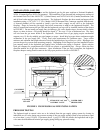
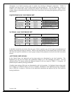
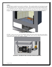
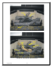
FIGURE 8 shows the rear burner tray assembly installed and sitting properly in the bottom of the Inglenook
Fireplace. Note that the gas tube of the rear burner must go through the slot in the right side of the floor and
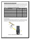
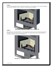
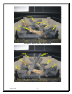
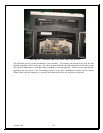
sit on top of the rear burner orifice mounted to the lower gas line. FIGURE 9 shows a close-up view of the
rear burner adjustable shutter gas tube being set over the gas orifice. It is important that the person
performing the installation ensure that the rear burner adjustable shutter tube is located properly over the
rear orifice. If the tube is not placed properly over the orifice, the burner assembly will not sit correctly into
the Inglenook Fireplace.
FIGURE 8: STEP 2 COMPLETE FIGURE 9: GAS TUBE


